If you design storm drains in Civil 3D, you probably know this loop. The pipe network lives in the drawing, but the hydraulic grade line lives in a spreadsheet. Every time the design changes, the numbers have to make the trip from one to the other and back again.
I ran that loop for years on rational method projects, one return period at a time. The math was never the hard part. The hard part was keeping the drawing and the calcs telling the same story. This post walks through where the round trip costs you, and how HydraStorm keeps the whole iteration inside Civil 3D.
The spreadsheet round trip
The traditional workflow looks something like this:
- Export pipe data from Civil 3D: lengths, inverts, sizes, rim elevations.
- Paste it into the HGL spreadsheet and line it up with the flows and junction loss coefficients.
- Compute the HGL from the outfall upstream and find the structures where it gets too close to the rim.
- Go back to Civil 3D and change the pipe sizes and inverts that failed.
- Export again, paste again, and check that the fix did not create a new problem upstream.
Some jurisdictions also want a check storm, so the loop runs again at the 25-year or 100-year event. Every pass is a chance for a transposed invert or a stale row. And at the end, the values in the drawing and the values in the report still have to be reconciled by hand.
Start from the network that is already in the drawing
HydraStorm runs inside Civil 3D 2025 and newer. Pick a pipe network from the toolbar, and it reads the pipes and structures directly: invert elevations, lengths, sizes, part families, rim elevations, and part descriptions. There is no export step.
Available pipe sizes come from the Civil 3D parts list assigned to the network, so every size you choose in HydraStorm is a real part that can be written back to the drawing.
Set up the design once
A few project settings replace the setup that usually gets rebuilt in each spreadsheet:
- Storm events. Declare the return periods the project uses, then give each one a role: Design, Check, or Analysis. Culverts and inlets can run at different storms than the pipe system. A storm frequency adjustment factor (Cf) can be set per return period.
- Hydrology. Enter peak flows directly, use the rational method with IDF data (NOAA Atlas 14, a CSV table, or b/d/e coefficients), or import basin results from HydraLink.
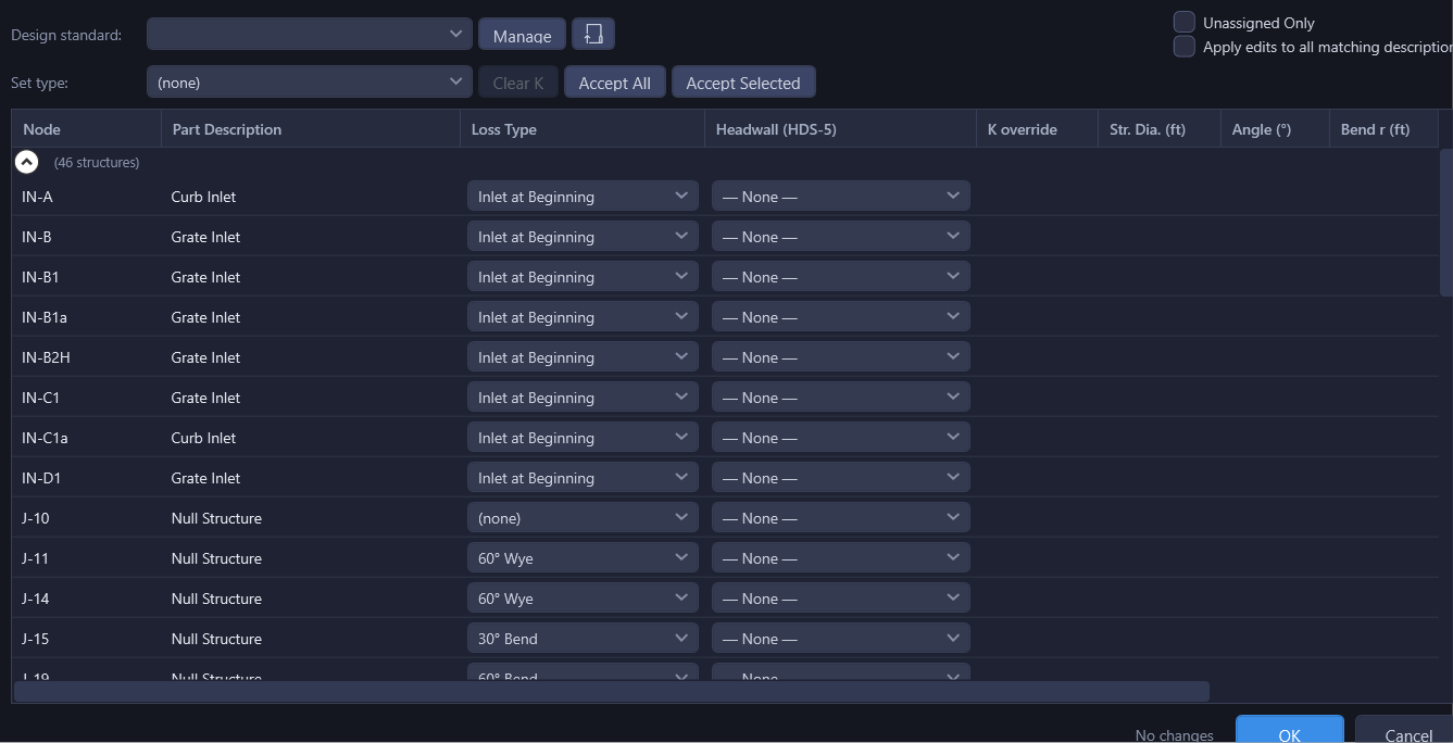
- Junction losses. Choose a design standard such as HEC-22, iSWM/NCTCOG, or a custom library for your municipality. HydraStorm suggests a loss type for each structure from its Civil 3D part description. Suggestions are never applied until you accept them.
Iterate where the design lives
Press F5 and HydraStorm computes flows from the headwaters down, then the HGL and EGL from the outfall up, with junction losses at every structure. Results fill the grid, and the profile view draws the HGL and EGL against the pipes and the ground.
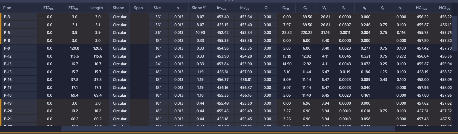
This is where the round trip disappears. Edit an invert, a slope, or a pipe size right in the results grid, and the results refresh a moment later. Every configured storm is recalculated on the same geometry, so the design storm and the check storm can never drift apart. A compliance column scores each pipe against your criteria, including velocity, cover, and HGL clearance, so the failures are visible without scanning a spreadsheet.
Tools for common edits are built in: raise or lower a run while holding its slope, set a slope from either end, or match inverts or crowns to the adjacent pipe. If you want a starting point, Auto Design proposes sizes and grades for an alignment against your design criteria, and you review the proposal before accepting any of it.
Nothing changes in the drawing until you apply
Every edit happens in a working copy with full undo and redo. You can try a larger trunk line or a deeper outfall, look at the HGL, and discard the whole idea without touching the drawing.
When the design is ready, click Apply. HydraStorm writes the geometry back to the Civil 3D pipe network (inverts, sizes, Manning's n, and part family changes). It also writes the calculated design storm results into the native Civil 3D properties:
- Pipes: HGL and EGL at each end, flow rate, return period, and the junction loss at the upstream structure.
- Structures: HGL, EGL, flow rate, and return period.
Because these are Civil 3D's own properties, your existing label styles and part list reports can show them directly. Apply again after the next revision and they update with it.
Plan production and the submittal
From the same session you can create HGL layout profiles in Civil 3D for the design storm, the check storm, or both, with each storm as its own named profile on the alignment. HydraStorm can also draft profile views and apply your label styles.
The spreadsheet still has a place, just not in the middle of the design. When you need calcs for a drainage report or a reviewer, export the Excel workbook. It includes storm drain, inlet, culvert, and compliance sheets with live formulas a reviewer can follow.
Try it on your own network
HydraStorm requires Autodesk Civil 3D 2025 or newer on 64-bit Windows. Every new account gets a 7-day free trial with all features, and no credit card is required. The install also includes sample projects if you want to explore before loading your own drawing.
Learn more on the HydraStorm product page, or start with the Getting Started guide. For details on the topics above, see Storm Events, Junction Losses, Applying Changes, and Export.