Storm Events
HydraStorm supports multiple storm events per project with independent return periods for each design module: storm drains, inlets, and culverts. Each module can have its own design storm and check storm, and each return period carries its own frequency adjustment factor (Cf).
Why Multiple Storms?
Many jurisdictions require analysis at two or more return periods, and different design elements may use different storms. Common requirements include:
- Storm drains: Size pipes for the 10-year storm; verify HGL clearance for the 100-year storm.
- Inlets: Check spread and depth at the 10-year storm; inlet capacity may use a different return period than the pipes.
- Culverts: Analyze headwater at the 50-year or 100-year storm, independent of the storm drain design event.
Rather than maintaining separate parallel calculations, HydraStorm runs all storms on the same network in a single analysis pass, guaranteeing consistency.
Storm Configuration
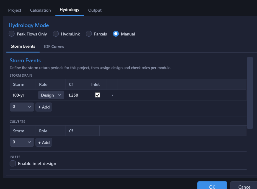
Storm configuration has two levels, on different tabs of Project Settings. The Hydrology tab declares which storms exist at all; the Storm Drain, Culverts, and Inlets tabs each pick which of those storms that module runs, and in what role.
1. Project Storm Events (Hydrology tab)
The Storm Events table on the Hydrology tab is where a return period first comes into existence. Each row has:
- Return Period (years): e.g., 2, 5, 10, 25, 50, 100
- Adjustment Factor (Cf): A multiplier on the runoff coefficient C for the rational method. Per TxDOT and FHWA guidance, Cf accounts for the reduced accuracy of the rational method at higher return periods. Typical values: 1.0 for storms up to 10 years, 1.1 for 25-year, 1.2 for 50-year, 1.25 for 100-year. Cf belongs to the return period, so it is entered once here and every module resolves its own value from it; the module storm grids described below show it read-only.
Adding a storm here only makes it available. A storm does nothing until a module below picks it up, and the IDF Curves sub-tab gets one intensity column per storm the moment it's added, so a municipal table can be filled in before any module is pointed at that return period.
2. Module Storm Lists (Storm Drain / Culverts / Inlets tabs)
Each module carries its own Storm Events grid, populated by picking from the periods declared on the Hydrology tab (a + Add combo lists only the ones that module doesn't already analyze) and assigning a role per row:
| Column | Meaning |
|---|---|
| Storm | The return period, read-only; add or remove periods on the Hydrology tab. |
| Role | Design, Check, or Analysis. Exactly one row may hold Design and one may hold Check; any number of the rest run as Analysis (HGL computed, no sizing or compliance verdict). The Storm Drain tab requires a Design row; Check is optional on all three tabs. |
| Route Capture (Storm Drain grid only) | Couples that storm's pipe flows to the inlet module's captured/bypass results (see Inlet Flow Coupling below). It does not choose the inlet design storm: that is the Inlets tab's own list, and the line under the Storm Drain grid says which storms the inlet module is rating. Greyed out while inlet design is off. Culverts and Inlets have no such column: only the Storm Drain pipe network has flows for inlet capture to feed into. |
A module's list can be left empty: Culverts and Inlets then run on the storm drain's own storm list, at the same roles. Leaving the storm drain list itself empty is not possible: it needs at least a Design row to compute anything.
3. Sizing Storm (Storm Drain tab)
Beside the storm drain's own grid, the Sizing Storm radio pair (shown once a check storm is enabled) controls which storm event the Auto Design engine uses when selecting pipe sizes:
| Option | When to Use |
|---|---|
| Design Storm | Most common. Size pipes to convey the design storm at or below full capacity. The check storm is used only for HGL verification. |
| Check Storm | Some jurisdictions require sizing to the check storm. This produces larger pipes that can convey the higher flows. |
How It Works
When multiple storms are defined, the calculation engine runs the full hydraulic pipeline for each storm event with completely independent results:
- Each storm uses its own IDF curve (different intensity at the same Tc for different return periods), and computes its own travel times and Tc.
- Each storm computes its own flows via the rational method (or uses separately provided peak flows).
- Each storm produces its own HGL/EGL profile through the pipe network.
- Inlet analysis runs its own storm list and feeds captured flows back into the pipe network only for the storm drain storms whose Route Capture column is checked.
- Culvert analysis computes headwater independently for each assigned storm event, and the culvert module's own storm list reaches the crossing numbers in every hydrology mode, including Peak Flows Only and imported-flow projects, not just rational ones. A culvert period the storm drain never publishes a flow for is reported by name rather than substituted from another storm. Enabling only the culvert check storm no longer also publishes a storm drain check storm at that period; the two stay independent.
- Where a culvert crossing's headwater sets the storm drain's water surface, it is taken at the storm drain's own return period, and an Info message names that storm.
- All storms share the same pipe geometry (sizes, slopes, inverts); only flow magnitudes and resulting hydraulic grade lines differ.
- Routed flows are resolved per storm. On the HydraLink Peak Flows basis, a pond's outflow replaces the upstream sum only for a return period the linked file actually published an outflow for; a storm the pond did not route takes no attenuation credit and accumulates conservatively instead.
Storm Frequency Adjustment (Cf)
The Cf factor is a multiplier on the runoff coefficient C per TxDOT and FHWA guidance. It accounts for the fact that the rational method can underestimate peak flows at higher return periods. Each return period has one Cf, entered in the Cf table on the Hydrology tab:
| Storm | Return Period | Cf | Effective C |
|---|---|---|---|
| Design | 10-year | 1.00 | C |
| Check | 100-year | 1.25 | 1.25 × C |
The resulting flow is: Q = Cf × C × I × A
Because the lookup is by return period, a module analysing a storm the storm drain isn't sized for still gets the right factor: a 100-year culvert check uses the 100-year Cf even when the trunk line is sized for the 10-year storm. See Frequency Adjustment (Cf).
Inlet Flow Coupling
When the inlet module is enabled, coupling is authored per storm drain storm, not by two project-wide checkboxes: on the Storm Drain tab's Storm Events grid, the Route Capture column checked on a row means that storm's pipe flows route actual inlet capture and bypass instead of assuming full interception at every structure (the conventional conservative method; the inlet module still rates spread and capture either way, only what feeds the pipes changes). Check it on the Design row, the Check row, both, or neither, independently.
This coupling allows the pipe network to carry only what the inlets actually capture, resulting in a more accurate (and often more economical) design.
Profiling
When creating HGL profiles in Civil 3D via Output → Create HGL Profiles…, you can choose to profile the design storm, the check storm, or both. Each storm produces its own named profile in the drawing:
Alignment1-HGL-10yr: design storm HGL profileAlignment1-HGL-100yr: check storm HGL profile
Both profiles reference the same pipe alignment, making it easy to compare hydraulic grade lines in the Civil 3D profile view.
Results
The Results Table displays columns for the selected storm. The storm drain results grid shows design storm values by default, with check storm columns visible when a check storm is configured. Key columns include:
- Q: peak flow (cfs)
- V: pipe velocity (ft/s)
- HGL DS / HGL US: hydraulic grade line elevations
- HGL Cover: clearance from HGL to rim or critical elevation
- Compliance: pass/fail summary for design criteria
Culvert results and inlet results appear in their own tabs with per-storm columns.
Consistency Guaranteed
- All storms run on the exact same network geometry, ensuring consistency across analyses.
- No manual synchronization between spreadsheets is required.
- When you change a pipe size or invert, all storms are recalculated automatically.
Note: In Peak Flows Only mode, and on the HydraLink Peak Flows basis, each storm carries its own directly entered or imported flow at each node. In the rational modes (Manual, and HydraLink on the Basin Parameters basis), each storm uses its own IDF curve and its return period's Cf to compute flows independently, and a directly entered flow is excluded from every storm.