Junction Losses
Junction losses represent energy loss at structures (manholes, inlets, bends, wyes) where pipes connect. Accurately modeling these losses is critical for a reliable HGL analysis. HydraStorm computes junction losses using a data-driven loss library system that supports multiple computation methods.
How Junction Losses Work
At each structure in your network, HydraStorm computes a head loss (hj) as part of the downstream-to-upstream HGL analysis. The loss is typically expressed as:
Where:
- Kj: Junction loss coefficient, determined by the assigned loss type
- V: Outlet pipe velocity (ft/s)
- g: Gravitational constant (32.174 ft/s²)
The computed head loss is added to the HGL at the downstream end of the structure, propagating the energy grade line upstream through the network.
Minimum loss: energy does not rise through a structure
Where the pipe leaving a structure runs faster than the main pipe arriving (flow joins and the pipe size stays the same, or a smaller pipe continues downstream), the water gains velocity head through the structure. The structure HGL must stand at least that much higher, or the energy grade line would rise in the downstream direction and every HGL upstream would be too low. HydraStorm holds the structure HGL at no less than the leaving pipe's upstream EGL minus the velocity head arriving, weighted by flow: water that enters at the structure itself brings no velocity head, and a lateral that drops in from above is credited its velocity only, not its fall. The main arriving pipe's own energy line is never allowed to rise through the structure either, which governs where a fast lateral joins a slow trunk. Where that governs, hj on the row includes the difference (the hj tooltip shows how much), and an informational message asks for a loss type that accounts for the velocity change.
A structure with no loss type assigned is the usual case. A loss written as K × Vo²/2g with a small K can also fall short where flow is added. Losses written as Vo²/2g − K × Vi²/2g already include the velocity change and are not affected. No pressure recovery is credited where the pipe below runs slower: the HGL is carried level and the velocity head given up is counted as lost.
Computation Methods
Each loss type in a library specifies one of three computation methods (Equation Kinds). The method determines how Kj and hj are calculated.
1. Expression String
A user-authored mathematical expression evaluated at calculation time. This is the most flexible method, allowing you to encode any formula using the available variables and functions.
Available Variables
| Variable | Description |
|---|---|
V_o | Outlet pipe velocity (ft/s) |
V_i | Dominant inlet pipe velocity (ft/s) |
V_l | Lateral inlet aggregate velocity (ft/s), average across all inlet pipes except the dominant |
Q_o | Outlet pipe flow (cfs) |
Q_i | Dominant inlet pipe flow (cfs) |
Q_l | Lateral inlet aggregate flow (cfs) |
D_o | Outlet pipe diameter (ft) |
D_i | Dominant inlet pipe diameter (ft) |
D_l | Lateral inlet aggregate diameter (ft) |
A_o | Outlet pipe full-barrel cross-sectional area (sq ft), shape-aware (circular or box) |
A_i | Dominant inlet full-barrel area (sq ft) |
A_l | Lateral full-barrel area, flow-weighted (sq ft) |
vh_o | Outlet velocity head: V_o² / (2g) |
vh_i | Inlet velocity head: V_i² / (2g) |
vh_l | Lateral velocity head: V_l² / (2g) |
theta | Deflection angle (degrees), from the structure's Deflection column in the Minor Losses table |
theta_rad | Deflection angle (radians) |
theta_l | Lateral deflection angle (degrees) |
theta_l_rad | Lateral deflection angle (radians) |
r_over_d | Bend radius ratio: the structure's bend radius ÷ D_o (used by 1D r/D bend tables, e.g. Austin Case 6) |
d_ratio | Diameter ratio: D_o / D_i (used by Brater & King enlargement/contraction tables) |
a_ratio | Area ratio: A_o / A_i (shape-aware, used by 2D area-ratio × velocity tables) |
b | Bench height (ft) |
d_ah | Access hole depth (ft) |
K | Loss coefficient from the loss type definition |
g | Gravity constant (32.174 ft/s²) |
pi | Pi constant (3.14159…) |
e | Euler's number (2.71828…) |
Available Functions
| Function | Description |
|---|---|
sin(x), cos(x), tan(x) | Trigonometric functions (input in radians) |
asin(x), acos(x), atan(x) | Inverse trigonometric functions (output in radians) |
atan2(y, x) | Two-argument arctangent (output in radians) |
sqrt(x) | Square root |
abs(x) | Absolute value |
pow(x, y) | Raise x to the power y |
min(x, y), max(x, y) | Minimum / maximum of two values |
ln(x) | Natural logarithm |
log10(x) | Base-10 logarithm |
deg2rad(x) | Convert degrees to radians |
rad2deg(x) | Convert radians to degrees |
vh(v) | Velocity head: v² / (2g) |
Example expression for a simple K-based loss:
The θ convention: HydraStorm follows HEC-22 convention for theta: 180° means straight-through (no bend at all), and 90° means a right-angle bend, so the angle decreases as the bend gets sharper. Write expressions with this in mind: a bend-loss formula should go to zero as theta approaches 180°, not to its maximum. K * sin(theta_rad / 2), for example, is backwards under this convention. It peaks at θ = 180° and would charge the largest loss to a straight run of pipe.
Example expression for an angle-dependent bend loss, from the built-in HEC-22 and iSWM/NCTCOG libraries (HEC-22 4th Ed Eq 9.6 / iSWM Eq 1.29, both AASHTO-derived: hb = 0.0033·Δ·V²/2g, where Δ is the bend's actual deflection in degrees):
Because 180° is straight, (180 - theta) recovers Δ, the actual angle of curvature, from HydraStorm's θ. At θ = 180° the expression correctly evaluates to zero.
2. HEC-22 Energy Loss Method (2nd Edition)
The FHWA HEC-22 2nd Edition (2001, FHWA-NHI-01-021) compound K method. The head loss is computed as:
Where the correction factors account for:
- Ko: Initial loss coefficient based on structure size relative to outlet pipe
- CD: Correction for pipe diameter changes
- Cd: Correction for flow depth
- CQ: Correction for relative flow (lateral vs. through flow)
- Cp: Correction for plunging flow
- CB: Correction for benching
These correction factors are computed automatically from the node geometry and connecting pipe properties. This method was retained verbatim in HEC-22 3rd Edition (2009) and removed in 4th Edition. It is still required by NCTCOG iSWM 2014 §1.2.10 (which reproduces the compound equations as Eq 1.36–1.42), so it backs the built-in iSWM / NCTCOG library and any user-created library that explicitly selects Hec22EnergyLoss2ndEd.
3. HEC-22 Energy Loss Method (4th Edition)
The FHWA HEC-22 4th Edition (2024, HIF-24-006) §9.1.6.7 Inlet and Access Hole Energy Loss Method. This replaces the 2nd Edition compound method for jurisdictions adopting the updated standard (e.g., TxDOT, recent FHWA federal projects).
The method computes the access hole energy level in three steps:
- Initial energy level: Eai = max(Eaio, Eais, Eaiu), the maximum of the outlet control, submerged inlet control, and unsubmerged inlet control analogies.
- Corrections (Eq 9.27): Ha = (CB + Cθ + CP)(Eai − Ei), adjustments for benching, angled inflow, and plunging inflow.
- Exit loss (Eq 9.31): Ho = 0.4 × Vo² / (2g), exit loss into the outlet pipe.
The total junction loss returned is (Ea − Ei) + Ho. All five benching types (Flat, Depressed, Half Bench, Full Bench, Improved) are supported. This method is used by the built-in HEC-22 Standard library and any library specifying the Hec22EnergyLoss4thEd equation kind.
Exit Loss at Outfalls
At an outfall node, HydraStorm can add an exit loss (Ke·V²/2g) on top of friction loss when the outfall carries a loss type or a manual Kj override. It's computed per-pipe and folded into Upstream HGL at that boundary, the same way junction losses are added moving upstream through the rest of the network, so an outfall with a headwall or a submerged discharge doesn't need a separate calculation outside HydraStorm to account for exit loss.
Deflection Angles
Bend, wye, and manhole deflection angles are stored per-structure, not per-library, in two channels: a trunk-through angle (theta/theta_rad, the dominant inlet pipe against the outlet pipe) and, separately, a lateral approach angle (theta_l/theta_l_rad, a wye's branch against the trunk). One library entry (e.g., "Bend") handles every possible angle via those variables in the expression; you never need a separate entry per angle.
The convention is HEC's: 180° = straight-through, 90° = a right-angle bend (see the note above). Angles come from your entry, the part description, or plan geometry:
- Your entry: an angle set directly on the structure (Minor Losses Table or property panel) always wins.
- The Civil 3D part description: a standard fitting angle named in the description is converted to HydraStorm's θ. A description naming a wye or lateral sets the lateral angle instead of the trunk angle, since the named angle describes the branch, not the trunk running through.
- Plan geometry: otherwise the angle is computed from the pipes at that structure. With nothing to go on, the structure is treated as straight-through (180°).
Separately, the Minor Losses Table can suggest a manufactured angle from CAD geometry: the nearest of the standard bend, wye, or manhole classes, offered whenever the geometry lands close to one. This is suggest-and-confirm: HydraStorm never stamps a suggested angle onto the structure on its own. Accept it to apply the value, same as accepting a suggested loss-type match.
Kj Lookup Tables
Some published manuals tabulate a discrete K value per angle (McKinney Table 4-14, Garland, Plano, MHFD's Figure 7-11, and others) rather than publishing a continuous formula. Rather than one library entry per angle, a loss type can carry a Kj lookup table: rows of (angle, K) that HydraStorm resolves against the structure's own deflection angle at calculation time, with either Nearest (returns the literal published K for the closest table row, the faithful choice for a discrete table) or Linear interpolation between rows. Tables can key off more than deflection angle alone: bend-radius ratio (r/D), diameter ratio, and area ratio are also supported axes, matching the way some manuals tabulate enlargement/contraction or curved-bend losses. Twelve of HydraStorm's eighteen built-in libraries use a Kj table for at least one entry.
Author a Kj table from the Equation Editor: check "Use a Kj lookup table," add rows, and use the built-in Test θ field to preview which K a given angle resolves to before you save.
Curved-Pipe (In-Barrel) Loss
A curved Civil 3D pipe (a barrel drafted along an arc rather than a straight tangent) can carry its own loss, separate from the junction losses at its structures. If your design standard defines a curved-pipe loss (the same AASHTO-derived hb = 0.0033·Δ·V²/2g form used in the bend example above, or a Kj-table equivalent keyed on the arc's central angle Δ and radius), HydraStorm applies it automatically to every curved barrel, using the arc geometry captured when the network is imported. There's nothing to assign per pipe, and splitting one curve into more drafted segments doesn't change the total loss reported for it.
This is a genuinely separate loss channel from the bend losses described above, which apply at a structure where pipes meet at a deflection. The curved-pipe loss applies along the barrel, added to Upstream HGL alongside friction loss, and appears as its own hb column in the results grid (visible only when your design standard defines a curved-pipe loss channel): US HGL = DS HGL + Friction Loss + Curve Loss + Exit Loss. Don't author a structure-level bend loss type to represent a conduit curve: if your library defines the curved-pipe channel, that would double-count the same physical bend once as a structure loss and once as a curve loss. A tangent curve (θ = 180° at both ends, no actual deflection) contributes nothing on either channel.
Expression Overrides
A loss type using ExpressionString can carry up to two optional expression overrides that take priority over the primary expression in specific flow regimes:
Partial Flow Override
The Partial Flow expression applies when the junction is free-surface: the outlet pipe is flowing partly full at the structure rather than under pressure. Use this override when a published standard gives different K values or formulas for partial vs. full-flow conditions.
With-Inflow Override
The With Inflow expression is used when the structure captures surface runoff (i.e., it is an inlet with local inflow of its own, such as flow or drainage area assigned at that structure, on top of what arrives in its pipes). This distinction is important because inlet structures with captured runoff behave differently from through-flow manholes, and many loss equations account for this with different coefficients.
When both overrides apply, Partial Flow is used; when neither applies, the primary expression is used.
Assigning Loss Types
There are several ways to assign loss types to structures in your network:
- Property panel: Select a pipe, then use the Junction Losses section of the property panel to assign a loss type to the upstream or downstream structure.
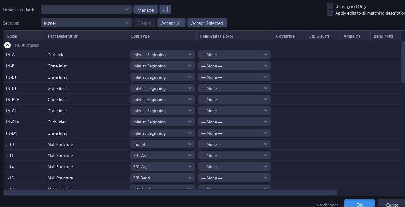
- Minor Losses Table: Open the Minor Losses Table from the Tables menu for bulk assignment across all structures in the network.
- Kj Override: Enter a manual Kj value in the property panel to override the loss type's computed coefficient. Leave blank to use the default computed value. Enter
0to force zero loss at a structure.
Auto-Matching
HydraStorm suggests a loss type for each structure automatically, by matching keywords in the Civil 3D part description. When you load a network, each structure's part description is matched against the loss types in the active library to find the best fit.
Each loss type carries its own explicit, editable list of keywords (each with a priority), authored in the Equation Editor's Keywords panel, not the type's display name or group. HydraStorm scans the part description for every keyword across the library's loss types; the highest-priority match wins. For example, a built-in Manhole entry carries keywords like "manhole," "junction," and "inlet" at different priorities, so a structure described "48 in Dia Concentric Manhole" matches on "manhole."
Smart Memory
When you manually assign a loss type to a structure, HydraStorm remembers that association between the part description and the loss type. This learning system is scoped per library, so assignments made while using a Frisco library do not affect matching when using a Dallas library.
Once you've consistently assigned the same loss type to a given part description, HydraStorm auto-applies that match in future projects. A single assignment isn't enough, and a description you've assigned inconsistently doesn't lock in.
For example: assign structures with the description "45 Deg Bend" to the "Bend" loss type across your projects, and later projects give "45 Deg Bend" structures the "Bend" loss type automatically.
What HydraStorm has learned is stored per user under %LocalAppData%\HydraStorm\. If a remembered choice points at a loss type you have since deleted, it is ignored and keyword matching takes over again.
Need a Library for Your Jurisdiction?
- HydraStorm ships with built-in libraries for HEC-22, iSWM/NCTCOG, and a general-purpose starter library.
- You can create custom libraries using the Loss Library Manager.
- Don't see a loss library for your jurisdiction? Contact support@bezaleldesignlab.com and we'll look into building one for you.