
HydraLink
Desktop Hydrology & Hydraulics Modeling
HydraLink is a desktop application for stormwater hydrology and hydraulics modeling. It supports complete watershed analysis from rainfall-runoff computation through detention design and hydraulic structure sizing. Built for civil engineers and stormwater designers.
Key Capabilities
Hydrologic Modeling
- Rational Method (Q = CiA) for peak flow estimation
- Modified Rational Method for detention volume sizing
- SCS Unit Hydrograph
- Multiple loss methods (SCS Curve Number, Green-Ampt)
- TR-55 time of concentration calculator
Hydraulic Analysis
- FHWA HDS-5 culvert analysis (inlet & outlet control)
- Manning’s equation for open channels (4 cross-section shapes)
- Road overtopping analysis
Detention Design
- Modified Rational Method required volume computation (Standard, iSWM, Atlanta Regional Commission methods)
- Modified Puls pond routing with full stage-storage-discharge analysis
- Multiple outlet structures: culverts, orifices, weirs, risers, spillways
Rainfall & Storm Design
- NOAA Atlas 14 data import
- IDF curve fitting (E, B, D coefficients) from Atlas 14 or user data
- Log-log and linear interpolation of Atlas 14 data
- SCS Type I/IA/II/III distributions
- Frequency Storm (alternating block)
- Custom storm distributions
Hydrograph Routing
- Muskingum-Cunge variable parameter routing
- Modified Puls (storage-indication) routing
- Lag (time translation) routing
- Kinematic Wave routing
- Multiple cross-section shapes (trapezoidal, rectangular, triangular, circular, 8-point)
Project Management & Data
- Plan management for comparing pre/post-development scenarios and design alternatives
- Linked elements shared across plans for efficient multi-scenario analysis
- Import basins from Civil 3D parcels (LandXML)
- Import drainage areas from GIS shapefiles
- Interactive map view with OpenStreetMap basemap
- PDF and DOCX report generation
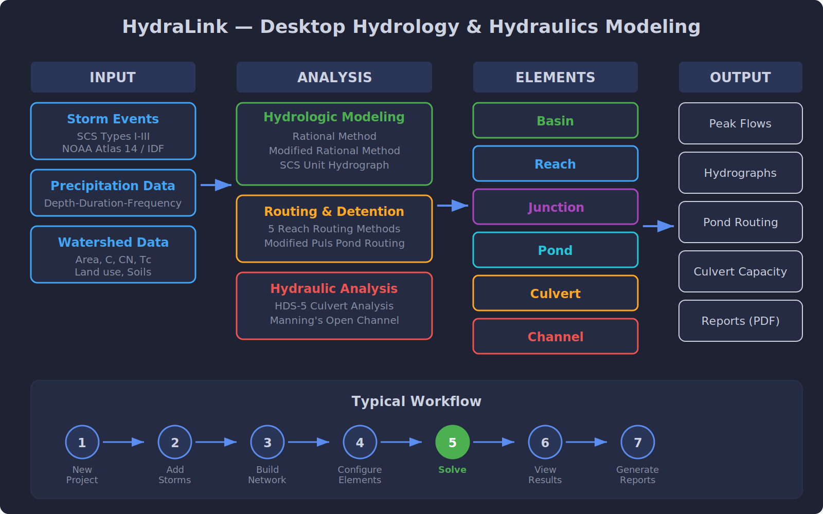
Element Types
- Basin — Generates runoff from rainfall (Rational, MRM, or Unit Hydrograph).
- Reach — Routes hydrographs through channels (routing methods).
- Junction — Combines flows from multiple upstream elements.
- Pond — Routes flow through detention/retention facilities.
- Culvert — Analyzes culvert capacity using HDS-5 methodology.
- Channel — Evaluates open channel capacity using Manning's equation.
Hydrologic vs. Hydraulic Elements
HydraLink includes both hydrologic and hydraulic element types. Understanding the distinction helps in building an effective model:
- Hydrologic elements (Basins, Reaches, Junctions, Ponds) are concerned with stormwater flows — how rainfall becomes runoff, how hydrographs travel through the drainage system, and how detention facilities store and release flow.
- Hydraulic elements (Culverts, Channels) are concerned with the physical flow properties of specific conveyance structures — capacity, headwater depth, velocity, flow regime, and whether a structure can convey the design flow.
HydraLink allows hydraulic elements to be calculated alongside the hydrology within a single program. This keeps all calculations in one place and allows changes to be dynamic — when the hydrology changes (e.g., updated basin areas or runoff coefficients), the hydraulic calculations automatically update as well.
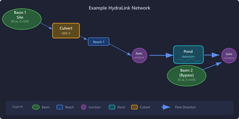
Practical Applications
Combining hydrologic and hydraulic elements in a single model is useful in many scenarios. For example, when designing large estate-style subdivisions with roadside ditches for stormwater conveyance, the hydrologic basins can be connected directly to the hydraulic channel or culvert elements. As the drainage design evolves, the hydraulic capacity analysis stays in sync with the changing hydrology.
Element Placement Guidance: When a hydraulic element (culvert or channel) needs to be analyzed in conjunction with a reach that provides hydrograph routing, the hydraulic element should be placed upstream of the reach (before the reach in the network). This ensures that the hydraulic element analyzes the peak flow rather than the attenuated (reduced) flow that results from reach routing.
Plan Management & Scenario Comparison
HydraLink’s plan management system allows engineers to quickly compare different drainage scenarios within a single project. Plans provide a powerful way to evaluate pre-development vs. post-development conditions, or to compare alternative design options.
- Multiple plans per project — Create separate plans for pre-development, post-development, and design alternatives. Each plan can have its own set of elements and configurations.
- Linked elements — Elements can be linked across plans so that parameters that stay the same (such as off-site basins, existing channels, or shared storm data) are automatically updated across all plans when edited in any one plan. This eliminates the need to manually synchronize common data between scenarios.
- Quick scenario switching — Switch between plans to compare results side by side, making it easy to evaluate different design alternatives.
Data Import
HydraLink supports importing drainage area data from external sources to accelerate project setup:
- Civil 3D Parcels (LandXML) — Import basins directly from Autodesk Civil 3D parcel data exported as LandXML files. Basin boundaries and areas are imported and displayed on the map view.
- GIS Shapefiles — Import drainage area boundaries from GIS shapefiles. Imported areas are displayed on the interactive map view for spatial reference and can be used to define basin elements.
Map View
HydraLink provides an interactive map canvas for spatial layout of your drainage network. Elements are placed and connected on the map, providing a visual representation of the drainage system topology. The map supports an OpenStreetMap basemap, zoom/pan navigation, and element repositioning by drag-and-drop.
Typical Workflow
- Create a new project
- Set up storm events and precipitation data (NOAA Atlas 14 or manual entry)
- Import basins from Civil 3D/GIS or add elements manually to the map
- Build the drainage network (connect elements downstream)
- Configure element properties
- Create additional plans for scenario comparison as needed
- Run the solver
- View results and hydrographs
- Generate reports (DOCX/PDF)
Worked Examples
Step-by-step walkthroughs that show HydraLink applied to real-world design problems. Each example includes the input parameters, configuration, and expected results so you can follow along and verify the methodology.
- MRM Example 1: City of Celina Detention Sizing — Modified Rational Method detention pond sizing for a 10-acre development, based on City of Celina, Texas design guidelines. Results match the City’s required detention volume.
Target Audience
Civil engineers, stormwater designers, and hydrology professionals performing drainage studies, detention design, and hydraulic analysis.