Getting Started with HydraStorm
This guide walks you through your first use of HydraStorm, from loading the plugin in Civil 3D to exporting a completed storm drain analysis. Follow these steps in order to get a working hydraulic model with results you can review and submit.
Prefer to explore first?
The samples folder in your install directory contains ready-to-open .hsp projects: sample-guided-tour (a minimal linear run), sample-culvert-crossing, and sample-hydralink-mode (a HydraLink-linked site), covering the peak-flow, culvert, and HydraLink hydrology modes. Open one via Load (no drawing required) and press F5 to calculate. See the README in that folder for what each sample demonstrates.
1 Install and Open HydraStorm
Download the HydraStorm installer from bezaleldesignlab.com and run it. Start Civil 3D 2025 or newer; HydraStorm loads automatically and adds a HydraStorm panel to the BDL ribbon tab (the one tab every Bezalel Design Lab product shares, so HydraLink and AutoStyle Pro sit beside it when they are installed). Click the HydraStorm button there, or type HYDRASTORM at the command line, to open the window. The tab comes back on its own after a workspace switch or CUI change. It floats alongside your drawing, so you can keep working in Civil 3D while it is open.
System requirements: Windows 10/11 (64-bit) and Autodesk Civil 3D 2025 or newer.
The first time you open the window, HydraStorm starts a Guided Tour: a spotlighted walkthrough of the interface using the bundled sample-guided-tour project. Replay it any time from Help > Guided Tour.... If your license isn't activated, a lock overlay covers the window until you activate from Help > Account....
2 Select a Pipe Network
In the HydraStorm toolbar, choose your pipe network from the Network dropdown. This reads all Civil 3D Pipe Network objects in the current drawing, along with pipe and structure geometry, inverts, sizes, part families, and part descriptions from the selected network.
If you modify pipes or structures in Civil 3D on the network you already have open, use the Refresh from CAD toolbar button (it lights up with a warning glyph when it detects an external change) rather than closing and reopening. See Refresh from Civil 3D. The same button re-reads the drawing’s network list, so a brand-new network added to the drawing appears in the Network dropdown after a refresh.

HydraStorm operates on one pipe network at a time. If your drawing contains multiple networks (e.g., separate storm systems), select each one individually to analyze it.
Before configuring hydrology, it's worth checking both items on the toolbar's Drawing menu: Network Issues (badged with a count when it finds something, such as orphaned basins, broken bypass targets, pass-through ponds, and other connectivity problems; rows click-navigate to the offending structure) and Clean Up Drawing (a suggest-and-confirm hub for drafting defects: reversed or zero-length pipes, missing reference alignments, alignments with no assigned run, and structure rims). Neither is required to proceed, but catching a drafting defect here is cheaper than chasing its symptom later in the results grid.
3 Configure Project Settings
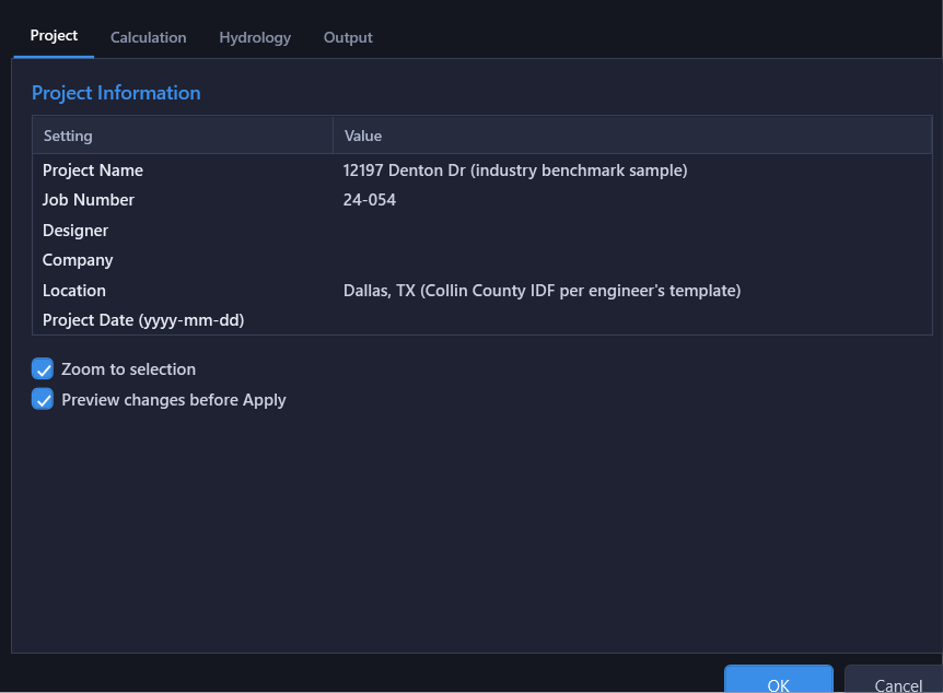
Click the Settings button in the toolbar to open the Project Settings dialog. Before running your first calculation, review these key settings:
- Hydrology Mode: Choose how design flows are determined:
- Peak Flows Only (default): enter Q directly at each structure
- HydraLink: import flows from a HydraLink project
- Manual: enter area, C, and Tc per node for rational method
- Storm Events: On the Hydrology tab, declare the return periods this project uses (one shared list). Then on each module's own tab (Storm Drain, Culverts, Inlets) pick from that list and assign a role (Design, Check, or Analysis) independently, so a culvert crossing can be checked at a different storm than the pipe system it feeds.
- Manning's n: Set the default roughness coefficient for new pipes on the Storm Drain tab.
The design standard (junction loss library, e.g., HEC-22, iSWM/NCTCOG, or a custom standard) is selected separately, from the Tables > Minor Losses... dialog. If the standard includes design criteria, you'll be prompted to apply municipality-specific defaults.
4 Set Alignment Design Types
Each alignment in your pipe network is classified as one of three design types:
- Storm Drain (default): Standard HGL/EGL calculation with junction losses
- Culvert: FHWA HDS-5 headwater analysis (see Culvert Analysis)
- None: Excluded from calculations
Set alignment types from Tables > Alignment Types... (Project Settings has no alignment-type controls of its own). If your network is all storm drain pipes, you can skip this step.
5 Set Up Hydrology
Enter design flows for each structure. The method depends on the hydrology mode you selected:
- Peak Flows Only: Enter Q (cfs) directly in the Hydrology Table or in the results grid. This is the simplest approach when you already have flows from an external source.
- HydraLink: Browse to your HydraLink project (
.hyd) in Project Settings > Hydrology. HydraStorm matches HydraLink basins and junctions to your pipe network structures by location: a basin goes to the structure at the marker you placed for it in HydraLink, and a junction to the structure at its block. A basin with no marker is left for you to assign. - Rational Method (Manual): First, configure your IDF data source (NOAA Atlas 14 fetch, CSV import, or manual b/d/e coefficients). Then enter the runoff coefficient (C), drainage area (acres), and time of concentration (Tc) for each node.
See Hydrology Modes for a detailed explanation of each mode.
6 Assign Junction Loss Types
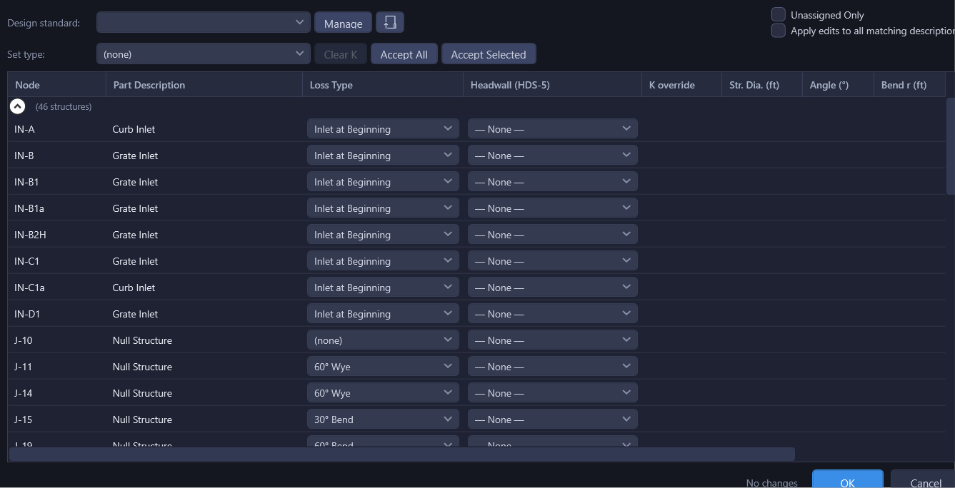
Open Tables > Minor Losses.... Each structure in your network needs a junction loss type that determines how energy losses are calculated at that node.
- Select a design standard from the dropdown: choose HEC-22, iSWM (NCTCOG), or a custom standard that matches your municipality's requirements.
- HydraStorm suggests a loss type for each structure based on its Civil 3D part description, using its smart memory system; suggestions are shown as a badge in the Suggestion column, never applied automatically.
- Click Accept All to accept every pending suggestion, Accept Selected to accept just the highlighted rows, or assign a Loss Type yourself from the dropdown in each row. As you confirm or correct assignments, HydraStorm learns your preferences for future projects.
Tip
Angles in the Minor Losses Table are the deflection from straight, the way a fitting is named: a "45 Degree Bend" is 45. A standard fitting class in the Civil 3D part description is auto-detected directly into the structure's angle at import: wye/lateral descriptions land on the Lateral Angle field, not the trunk. Angles measured from the actual pipe geometry are only ever suggested, within 5° of a standard fitting (22.5/30/45/60), never applied automatically; accept them from the Angle Suggestion badge in the Minor Losses Table. A bend, wye, or direction-change manhole with no angle entered shows its Angle cell in orange until you confirm one. (Loss library equations keep the HEC-22 θ convention, 180° = straight; the table converts for you.)
7 Configure Inlets (Optional)
If your project requires inlet capacity analysis, switch to the Inlet tab and click Library... to select an inlet library (e.g., HEC-22, iSWM, or municipality-specific). Then, for each inlet:
- Assign an inlet type, specifying whether it's a sag or on-grade inlet.
- Configure gutter cross-section geometry per inlet, or apply a roadway template.
- Set bypass routing targets for each inlet.
8 Calculate
Press F5 (there is no dedicated Calculate button; results also refresh automatically a moment after you finish editing a property). HydraStorm runs the full analysis in order:
- Flow computation (upstream to downstream): Accumulates flows through the network, working from the headwaters toward the outfall.
- Inlet analysis (if enabled): Computes capture and bypass at each inlet, feeding captured flows into the pipe network.
- HGL/EGL analysis (downstream to upstream): Propagates hydraulic grade line and energy grade line from outfall boundary conditions toward headwaters.
- Culvert analysis (if culvert alignments exist): Computes HDS-5 headwater for culvert pipes.
- Compliance evaluation: Checks each pipe against design criteria (velocity, cover, HGL clearance).
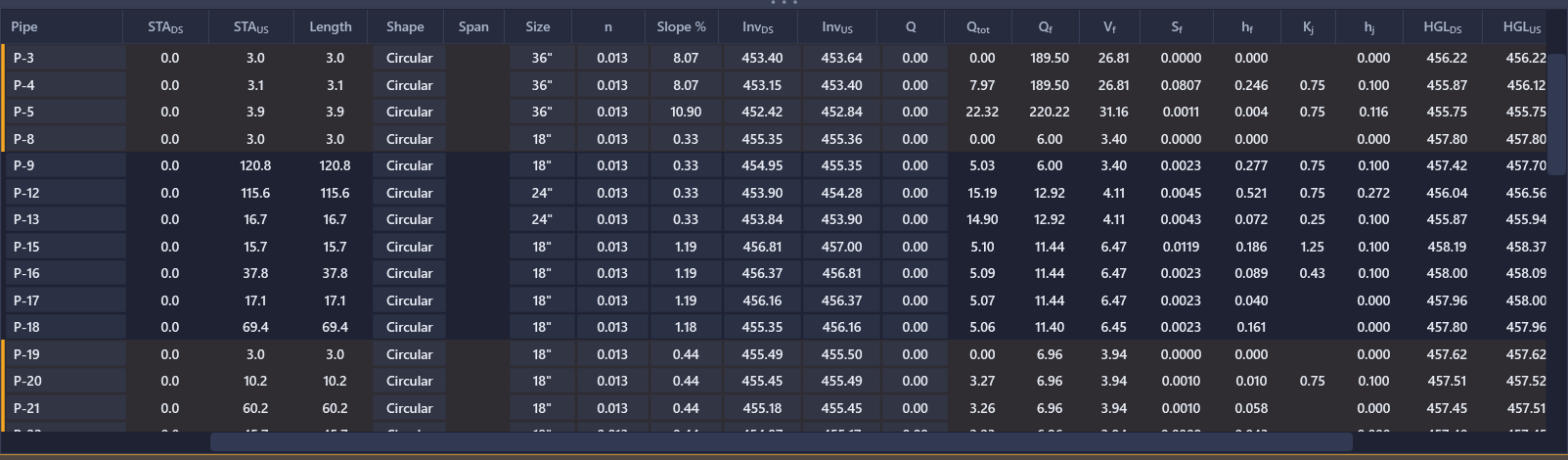
Results appear immediately in the results grid, and the profile view updates to show the computed HGL and EGL lines.
9 Review Results
Examine the results grid for any issues. HydraStorm tracks compliance with color-coded indicators:
- Green: All design criteria pass
- Yellow: Some failures, but all have been reviewed and acknowledged
- Red: Unresolved compliance failures (e.g., HGL above rim, velocity out of range, insufficient cover)
The Comply column shows a score like "4/6" (4 of 6 checks passed). Hover for details on each check. If a failure is intentional, right-click the pipe and choose Acknowledge Check Failures....
In the profile view, toggle these overlays to visualize the hydraulic analysis:
- HGL: Hydraulic Grade Line (water surface)
- EGL: Energy Grade Line (total energy)
- Ground: Existing ground surface along the alignment
- Crossings: Utility crossings with clearance violations highlighted
10 Edit and Iterate
Adjust pipe parameters to resolve compliance issues. Inverts, size, slope, and Manning's n are edited directly in the results grid; shape, part family, and junction loss type are edited in the property panel next to the profile. The profile and calculations update live as you make changes.
Use the editing tools for efficient adjustments:
- Raise / Lower (
Ctrl+Shift+R): Shift both inverts uniformly (preserves slope) - Set Slope (
Ctrl+Shift+L): Apply a specific slope with anchor selection - Match to Adjacent: Align inverts, crowns, or centerlines with the neighboring pipe (right-click context menu)
- Match Slope (
Ctrl+M): Set a continuous slope across multiple selected pipes
11 Auto Design (Optional)
Click Auto (in the property panel) to let HydraStorm suggest pipe sizes that satisfy your design constraints. Auto Design runs its own calculation internally, so there's no need to press F5 first. The sizing engine selects the smallest standard pipe size from the active parts list that meets capacity, velocity, and HGL cover requirements. If a size choice leads to an HGL violation, Auto Design revises it before finishing. Sizing applies to the alignment currently shown in the profile view; pipes on other alignments keep their sizes and act as fixed hydraulic context.
Two dialogs may appear before sizing starts: a scope prompt if you have several pipes selected (size just the selection, or the whole run), and a start-elevation prompt letting you set or accept the invert at each outfall/scope tie-in the walk anchors from. Neither is shown when it has nothing to ask: e.g. no multi-pipe selection, or Auto Design Grades is set to Hold Existing Grades.
Review the suggested sizes, then click Apply (in the property panel) to accept or Discard to revert. See Auto Design for details.
12 Apply Changes to Civil 3D
When you are satisfied with your design, click Apply (pinned at the bottom of the property panel) to write all edits back to the Civil 3D pipe network objects. This updates pipe invert elevations, pipe sizes, and Manning's n values, along with anything else you changed in the session: part family/size swaps, structure rim elevations, junction loss values (the pipe's Junction Loss property), and any run-aware renames from Drawing > Rename Parts by Run....
If you need to undo your changes, click Discard to revert to the last applied snapshot.

Tip
HydraStorm uses an Edit Session pattern: all your changes are made to a working copy. Nothing is written to Civil 3D until you explicitly click Apply. This means you can freely experiment without risk to your drawing.
13 Create Profiles and Labels
Once your design is finalized and applied to Civil 3D, open the Output ▾ menu in the toolbar:
- Create HGL Profiles... opens an options dialog: pick the storm(s) to profile (Design, Check, or Both, hidden when the project has no check storm), a profile style (or leave at "(automatic)" to match an existing profile on the alignment), then click Create HGL Profiles for the full water-surface profile (includes the gradually-varied-flow surface inside pipes flowing partially full) or Create Simple HGL for PVIs at just each pipe's upstream/downstream HGL and structure HGL; use Simple HGL when you plan to label profile PVI points, since the full surface would place a label at every curvature point.
- Apply Label Styles applies your configured pipe and structure label styles to the profile views, annotating sizes, slopes, inverts, and lengths.
See Profiles & Labels for details on configuring label styles and profile view options.
14 Export Results
From the Output ▾ menu, click Export > Excel Workbook... to write the full calculation workbook for verification or submittal: storm drain, inlet, culvert and compliance sheets, with live formulas a reviewer can follow. (The older CSV dumps were removed in September 2026; save a sheet as CSV from Excel if another tool needs one.)
See Export for details on the export format and customization options.
Tips for Success
- Keyboard shortcuts:
F5= Calculate,Ctrl+Z= Undo,Ctrl+S= Quick Save,Ctrl+F= Fit Profile,Arrow keys= navigate pipes - Save frequently: HydraStorm project files (
.hsp) store all your settings, flows, and loss type assignments independently from the Civil 3D drawing. - Auto Design runs its own calculation: you don't need to press F5 first; it establishes flow data itself before sizing.
- Design criteria prompting: When you select a design standard with built-in criteria, HydraStorm prompts you to apply municipality-specific defaults (storm periods, velocity limits, cover, etc.). Accept or decline each recommendation individually.