Basin Element
The Basin element represents a drainage area that generates runoff from rainfall. It is the fundamental source element in every HydraLink network. Basins support three rainfall-runoff methodologies: Rational Method, Modified Rational Method (MRM), and Unit Hydrograph.
When to Use
- Every HydraLink network starts with one or more Basin elements.
- Rational Method — Quick peak flow estimates for small watersheds, storm sewer design, and inlet sizing.
- Modified Rational Method — Detention pond sizing for small watersheds using a simplified volumetric approach.
- Unit Hydrograph — Full hydrograph generation for detention routing, complex networks, and watersheds of any size.
Input Parameters
Rational Method Parameters
| Parameter | Units | Description | Notes |
|---|---|---|---|
| Runoff Coefficient (C) | dimensionless | Weighted C value (0–1) representing the fraction of rainfall that becomes runoff | Computed from land use breakdown or entered directly. Should be based on local municipality requirements. |
| K Factor | dimensionless | Frequency/safety adjustment factor | Default 1.0. Some jurisdictions require a storm adjustment factor (K) that varies for different storm events. |
The Rational Method computes: Q = K × C × i × A where
i = rainfall intensity (in/hr) at duration = Tc. Intensity is resolved
from (in priority order): fitted IDF curve coefficients (e, b, d),
NOAA Atlas 14 direct intensity interpolation, or total depth / duration as a fallback. See the
Rational Method and
Storm Events pages for details.
Modified Rational Method Parameters
All Rational parameters plus:
| Parameter | Units | Description | Notes |
|---|---|---|---|
| Detention Method | — | Standard or Regional IDF Table (iSWM / Atlanta Regional Commission) | See MRM methodology for details on each method |
| Basin Role | — | Design Area, Target, Bypass, or Pass-Through | Assigned when basins are added to the MRM analysis; can be linked to elements in the model so as the design evolves the detention calculations are quickly updated |
| County / Region | — | County (TX iSWM) or city (GA Atlanta Regional Commission) selection | Required when using the Regional IDF method; provides region-specific a and b rainfall coefficients |
MRM is a required volume computation only. It determines the minimum detention storage volume needed but does not perform hydrograph routing. The outfall structure should be designed such that the design flow is less than the allowable release rate for the design storm event. Care should be taken not to over-detain, as there is no check that the pond releases enough flow to prevent overtopping. See the Modified Rational Method page for full details.
MRM Basin Roles
- Design Area
- Post-development area detained in the pond. Its C and area contribute to the composite detained inflow.
- Target
- Represents pre-development conditions. Its peak flow defines the allowable release rate for the pond.
- Bypass
- Flow from the developed site that does not enter the detention pond. This flow reduces the allowable release from the pond, increasing the required detention volume.
- Pass-Through
- Off-site flow that enters the pond but is not detained. Since this is an existing flow, detention is not needed for it, but the outfall structure must be sized larger to convey pass-through flow in addition to the allowable detained release.
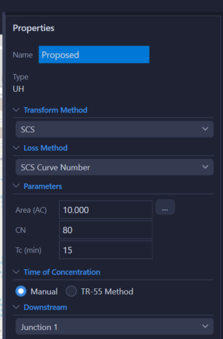
Unit Hydrograph Parameters
| Parameter | Units | Description | Notes |
|---|---|---|---|
| Curve Number (CN) | dimensionless | SCS curve number (0–100) representing runoff potential | Computed from soil-cover breakdown or entered directly |
| Transform Method | — | SCS Unit Hydrograph | Determines the shape of the unit hydrograph. (Clark, Snyder, and ModClark transforms are planned but not currently active.) |
| Loss Method | — | SCS Curve Number or Green-Ampt | Determines how rainfall losses are computed |
Transform-Specific Parameters
SCS Curvilinear
Uses Tc to derive lag time: tlag = 0.6 × Tc.
Peaking factor is configurable (default 484).
Additional transform methods (Clark, Snyder, ModClark) are planned for future releases but are not currently active. The SCS Curvilinear unit hydrograph is the available transform method at this time.
Loss Method Parameters
SCS Curve Number
Uses CN to compute initial abstraction:
No additional parameters beyond CN.
Green-Ampt
| Parameter | Units | Description |
|---|---|---|
| Hydraulic Conductivity (K) | in/hr | Saturated hydraulic conductivity of the soil |
| Wetting Front Suction (ψ) | in | Capillary suction at the wetting front |
| Initial Moisture Deficit (Δθ) | 0–1 | Difference between porosity and initial moisture content |
Values can be looked up by USDA soil texture class.
Land Use Breakdown & Weighted C
HydraLink provides a customizable land use table where you enter the area and C value for each land cover type. The weighted C is computed as:
Soil-Cover Breakdown & Weighted CN
For the Unit Hydrograph method, enter the area, cover type, treatment, hydrologic condition, and hydrologic soil group (A, B, C, D) for each soil-cover combination. The weighted CN is:
CN values are from TR-55 Tables 2-2a/b/c for Antecedent Moisture Condition II. The built-in CN lookup dialog provides the full TR-55 table.
Time of Concentration (Tc)
HydraLink includes a TR-55 flow path calculator for computing Tc. The flow path is divided into segments:
- Sheet Flow — Maximum 300 ft. Uses Manning's n for overland flow surfaces.
- Shallow Concentrated Flow — Paved or unpaved surfaces.
- Channel Flow — Uses Manning's equation with channel geometry.
Tc = sum of travel times for all segments. See the Time of Concentration methodology page for full details.
Results
| Output | Units | Description |
|---|---|---|
| Peak Flow | cfs | Maximum runoff rate |
| Time to Peak | hours | Time from start of storm to peak flow |
| Runoff Volume | acre-ft | Total volume of runoff (UH method only) |
| Hydrograph | cfs vs. time | Full runoff hydrograph (UH method only; Rational produces peak flow only) |
| MRM Detention Volume | ft³ | Required storage volume (MRM method only) |
| MRM Critical Duration | minutes | Storm duration producing maximum required storage (MRM method only) |
Methodology Considerations
- The Rational Method produces a peak flow only (no hydrograph). It is commonly used for storm sewer design, inlet sizing, and small watershed analysis. Its applicability depends on local jurisdictional criteria.
- The Unit Hydrograph method generates a full runoff hydrograph and is needed when routing through ponds, channels, or complex networks.
- The Modified Rational Method provides a required detention storage volume using a simplified volumetric approach. The MRM does not perform hydrograph routing — the engineer must independently design the outfall structure.
- The appropriate methodology for a given project depends on local design criteria, jurisdictional requirements, and the engineer’s professional judgment.
- For developed sites, ensure your C coefficient reflects post-development conditions.
- The SCS Peaking Factor (default 484) can be adjusted in Project Settings for different regional practices.