Reach Routing Methods
Overview
Reach routing simulates the movement of a flood wave through a channel or conduit. As a hydrograph travels through a reach, two effects occur: translation (the hydrograph is delayed) and attenuation (the peak is reduced and the hydrograph is spread out). Different routing methods model these effects with varying levels of detail.
Method Comparison
| Method | Translation | Attenuation | Parameters | Physical Basis | Computational Cost |
|---|---|---|---|---|---|
| Lag | Yes | No | Lag time | None | Very Low |
| Muskingum-Cunge | Yes | Yes | Channel geometry | Physics-based | Low |
| Modified Puls | Yes | Yes | Storage-discharge table | Empirical | Medium |
| Kinematic Wave | Yes | Limited | Channel geometry | Physics-based | Medium |
Lag Method
The simplest routing approach. Shifts the inflow hydrograph forward in time by a fixed lag time. No attenuation occurs — the outflow hydrograph has the same shape and peak as the inflow, only translated (shifted) in time.
Regional Consideration: Lag routing does not attenuate the flow — it only translates the hydrograph in time. This is typically used for relatively short reaches where the travel time is small relative to the hydrograph duration and where channel storage effects are negligible. For longer reaches or reaches where storage effects are significant, a routing method that provides attenuation (such as Muskingum-Cunge or Modified Puls) may be more appropriate. The engineer should evaluate whether lag routing adequately represents the physical system for the given application, considering local design criteria and site conditions.
Muskingum-Cunge Method
Derives Muskingum K and X parameters from physical channel properties, eliminating the need for calibration. This method is widely used for open channel routing when channel geometry is known.
Process
- Choose a reference flow (typically the inflow peak)
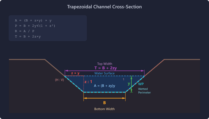
- Solve Manning's equation for normal depth at Qref using the trapezoidal channel geometry (bottom width B, side slope z, slope S, Manning's n)
- Compute wave celerity:
c = (5/3) × V(for wide channels, based on Manning's equation) - Compute
K = Length / c - Compute
X = 0.5 × (1 − Q / (T × c × S × Length))where T = top width at normal depth
Not appropriate for: backwater-affected reaches, very flat slopes (S < 0.0001), tidally influenced areas, reaches with significant floodplain storage, or supercritical flow conditions. In these cases, use Muskingum with calibrated parameters.
Modified Puls (Storage-Indication) Method
Uses a known storage-discharge relationship to route the hydrograph.
Storage Indication Curve
Routing
At each time step, interpolate O from the SI curve. This method is suitable for reaches where the storage-discharge relationship is known from field data or detailed hydraulic modeling.
Kinematic Wave Method
Assumes the momentum equation reduces to a balance between friction and gravity (kinematic approximation). Uses the same channel geometry as Muskingum-Cunge.
Best for steep channels (S > 0.01) where inertial and pressure gradient terms are small. Not suitable for backwater effects or very flat slopes.
Selecting a Routing Method
The appropriate routing method depends on the site conditions, available data, and local design criteria. The following considerations may help guide the selection:
- Lag — Appropriate for relatively short reaches where attenuation is negligible. Provides translation only (no peak reduction). The engineer should consider whether neglecting attenuation is appropriate for the given reach length and conditions.
- Muskingum-Cunge — Commonly used when channel geometry is known but calibration data is unavailable. Derives routing parameters from measurable channel properties.
- Modified Puls — Appropriate when the storage-discharge relationship is known from field data or detailed hydraulic modeling (e.g., wide floodplain sections).
- Kinematic Wave — Suited for steep channels where inertial and pressure gradient terms are small.
The selection of a routing method is an engineering judgment decision. Local design criteria, jurisdictional requirements, and the physical characteristics of the reach should all be considered when selecting a method.
References
- Cunge, J.A. (1969). “On the Subject of a Flood Propagation Computation Method.” Journal of Hydraulic Research.
- USACE (2000). HEC-HMS Technical Reference Manual.
- Chow, V.T. (1959). Open-Channel Hydraulics. McGraw-Hill.