Reach Element
Overview
The Reach element represents a channel or conduit that conveys and routes flow from upstream to downstream. Reaches model the translation (delay) and attenuation (peak reduction) of hydrographs as they travel through the drainage system. HydraLink supports four routing methods, each suited to different situations.
When to Use
- Between any two elements where flow is conveyed through a channel, pipe, or overland flow path
- When hydrograph attenuation and translation through a channel segment is important
- For modeling the effect of channel geometry on hydrograph shape
Routing Method Comparison
| Method |
Complexity |
Attenuation |
Best For |
Requires |
| Lag |
Low |
None |
Short reaches, quick estimates, preliminary analysis |
Lag time only |
| Muskingum-Cunge |
Medium |
Yes |
Open channels where geometry is known and calibration data is unavailable |
Channel geometry (length, slope, Manning's n, bottom width, side slope) |
| Modified Puls |
Medium |
Yes |
Reaches where storage-discharge relationship is known |
Storage-discharge table |
| Kinematic Wave |
Medium |
Yes |
Steep channels where other methods may be unstable |
Channel geometry |
Input Parameters
Lag Method
| Parameter |
Units |
Description |
Notes |
| Lag Time |
minutes |
Time delay applied to the hydrograph |
Hydrograph shape is preserved unchanged; only shifted in time |
Regional Consideration: The Lag method provides no attenuation —
it translates (time-shifts) the hydrograph without reducing the peak flow. The outflow hydrograph is
identical to the inflow hydrograph, just shifted by the lag time. This approach is typically used for
relatively short reaches where the travel time through the reach is small relative to
the overall hydrograph duration, and where storage effects within the reach are negligible. Regional
design criteria and the engineer’s judgment should guide whether lag routing is appropriate for
a given application. For longer reaches or reaches where channel storage may significantly affect
hydrograph shape, a routing method that accounts for attenuation (such as Muskingum-Cunge or
Modified Puls) may be more appropriate.
Muskingum-Cunge Method
| Parameter |
Units |
Description |
Notes |
| Length |
ft |
Reach length |
Measured along the channel centerline |
| Slope |
ft/ft |
Channel bed slope |
Positive value, typically 0.001–0.05 |
| Manning's n |
dimensionless |
Roughness coefficient |
See standard tables; typical 0.03–0.05 for natural channels |
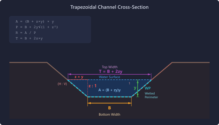
| Bottom Width |
ft |
Width of channel bottom |
For trapezoidal cross-section |
| Side Slope |
H:V |
Horizontal to vertical side slope ratio |
e.g., 3 means 3 ft horizontal per 1 ft vertical |
How it works: Muskingum-Cunge automatically computes K and X from the channel geometry. For a reference flow (Qref), it solves for normal depth, then computes wave celerity c = (5/3) × V, K = Length / c, and X = 0.5 × (1 − Q / (T × c × S × L)).
Note: Muskingum-Cunge derives routing parameters directly from measurable channel
properties (geometry, slope, roughness), eliminating the need for calibration data. It is widely used
for open channel routing applications. However, the appropriate routing method for any given project
depends on the engineer’s judgment, local design criteria, and site conditions.
Applicability Considerations: Muskingum-Cunge may not be appropriate for:
backwater-affected reaches, very flat slopes (S < 0.0001), tidally influenced areas, or
reaches with significant floodplain storage. In these cases, other methods such as Modified Puls
with a known storage-discharge relationship may be more suitable. The engineer should evaluate the
site conditions and select the routing method that best represents the physical system.
Modified Puls Method
| Parameter |
Units |
Description |
Notes |
| Subreaches |
— |
Number of subreaches |
Divides storage-discharge among subreaches |
| Storage-Discharge Table |
acre-ft vs cfs |
Paired storage and discharge values |
Defines the relationship between reach storage and outflow |
The Modified Puls method uses the storage-indication approach: (2S/Δt + O) is plotted against O. For each time step:
SIj+1 = Ij + Ij+1 + SIj − 2Oj
Outflow is interpolated from the SI curve.
Kinematic Wave Method
| Parameter |
Units |
Description |
Notes |
| Length |
ft |
Reach length |
Same geometry inputs as Muskingum-Cunge |
| Slope |
ft/ft |
Channel bed slope |
Works best for steep slopes |
| Manning's n |
dimensionless |
Roughness coefficient |
|
| Bottom Width |
ft |
Channel bottom width |
|
| Side Slope |
H:V |
Side slope ratio |
|
Note: Kinematic Wave assumes a simplified wave propagation model. It works best for steep channels where the Froude number is high and diffusion effects are minimal.
Results
| Output |
Units |
Description |
| Peak Inflow |
cfs |
Maximum inflow to the reach |
| Peak Outflow |
cfs |
Maximum routed outflow |
| Attenuation |
cfs |
Peak inflow minus peak outflow |
| Time to Peak |
hours |
Time of peak outflow |
| Routed Hydrograph |
cfs vs. time |
Full outflow hydrograph |
Tips & Best Practices
- Muskingum-Cunge is commonly used when channel geometry is known and calibration data is unavailable. The appropriate routing method depends on site conditions and local design criteria.
- Modified Puls is often used when you have survey data defining the storage-discharge relationship of a reach (e.g., a wide floodplain section).
- Reach length should be measured along the channel thalweg, not as a straight-line distance.