Pond Routing
Overview
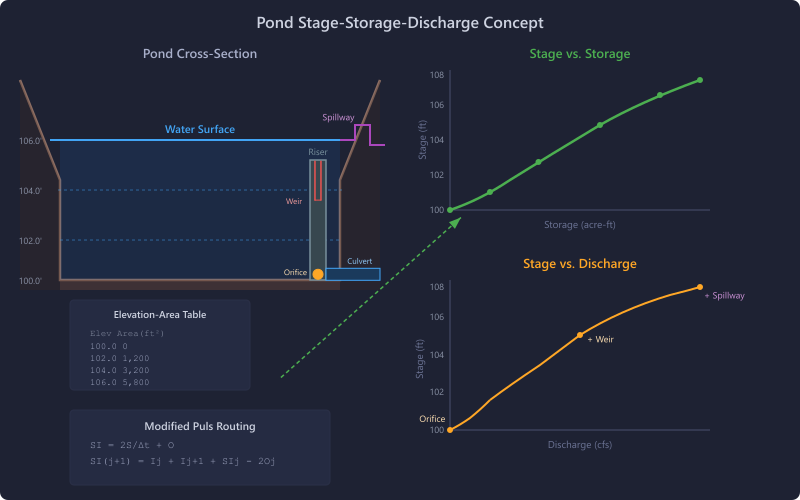
Pond routing determines how an inflow hydrograph is attenuated as it passes through a detention or retention facility. HydraLink uses the Modified Puls (level pool) routing method for ponds, combined with a stage-storage-discharge relationship defined by the pond geometry and outlet structures.
Modified Puls Method
Theory
The Modified Puls method assumes level pool conditions — the water surface in the pond is horizontal at all times. This is valid for ponds where the inflow rate is small compared to the pond surface area.
Routing Procedure
- Compute the stage-storage-discharge table by evaluating all outlet structures at each elevation in the storage table
- Compute the storage-indication curve:
SI = 2S/Δt + Oat each stage - For each time step:
SIj+1 = Ij + Ij+1 + (SIj − 2Oj)- Interpolate Oj+1 from the SI vs O relationship
- Compute stage and storage from the stage-storage-discharge table
- Track peak stage, peak outflow, and timing
Stage-Storage-Discharge Computation
At each elevation in the storage table:
- Storage S = cumulative volume from the lowest elevation
- Discharge O = sum of all outlet flows:
- Culvert flow (HDS-5 analysis)
- Orifice flow:
Q = Cd × A × √(2gh)for each orifice where h = stage − orifice center elevation - Weir flow:
Q = Cw × L × H3/2for each weir where H = stage − weir crest elevation - Riser top overflow when stage exceeds riser top
- Spillway flow at higher stages
MRM Detention Sizing
For basins using the Modified Rational Method, the pond can perform a simplified detention sizing analysis without requiring a full stage-storage-discharge relationship.
See the Modified Rational Method methodology page for details.
Outlet Structure Hydraulics
Culvert (Primary and Secondary)
Full HDS-5 analysis. See the Culvert element page.
Riser Structure
The riser acts as a vertical pipe or box with multiple openings at different elevations.
Orifice Equations
- Circular:
A = π/4 × D²,Q = Cd × A × √(2gh), default Cd = 0.6 - Rectangular:
A = W × H, same discharge equation
Weir Equations
Top Overflow
When water overtops the riser, effective weir length = riser perimeter − sum of weir widths.
Spillway Types
| Type | Equation | Notes |
|---|---|---|
| Sharp-Crested Rectangular | Q = Cw × L × H3/2 | Standard sharp-crested weir |
| Broad-Crested Rectangular | Q = Cw × L × H3/2 | Lower Cw than sharp-crested |
| V-Notch (90°) | Q = Cv × H5/2 | For low-flow measurement |
| Cipolletti | Q = Cw × L × H3/2 | Trapezoidal weir (1H:4V sides) |
Design Considerations
- The primary outlet (culvert or riser orifices) controls outflow for frequent storms
- Weirs and spillways activate at higher stages for larger storms
- The spillway should be sized to pass extreme events without overtopping the embankment
- Total outflow is the sum of all outlet structure discharges at each stage
References
- NRCS (2010). National Engineering Handbook, Part 630, Chapter 17 — Flood Routing.
- FHWA (2001). Urban Drainage Design Manual, HEC-22.
- Akan, A.O. (1993). Urban Stormwater Hydrology. Technomic Publishing.