Plans & Scenarios
Overview
HydraLink’s plan management system enables engineers to compare multiple drainage scenarios within a single project file. Plans are commonly used to evaluate pre-development vs. post-development conditions, compare design alternatives, or test different configurations without duplicating data.
What is a Plan?
A plan is a self-contained configuration of hydrologic and hydraulic elements within a project. Each plan defines its own drainage network with its own set of elements, connections, and parameters. A single HydraLink project can contain multiple plans, and the solver runs each plan independently.
Common uses for multiple plans include:
- Pre-development vs. post-development: model existing conditions and proposed conditions side by side to compare peak flows, runoff volumes, and detention requirements.
- Design alternatives: evaluate different pond sizes, outlet configurations, routing approaches, or development layouts.
- Phased development models interim and ultimate build-out conditions.
Linked Elements
When multiple plans share common elements, such as off-site basins or existing channels that do not change between scenarios, HydraLink allows those elements to be linked across plans.
How Linked Elements Work
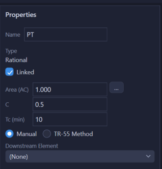
- A linked element exists in multiple plans but shares a single set of properties.
- When you edit a linked element’s parameters in any plan, the changes are automatically reflected in all plans that share that element.
- This eliminates the need to manually update common data across scenarios and ensures consistency.
- To link an element, tick Share across plans in its properties panel, or right-click it on the map and choose Link to Plan (Copy to Plan makes an independent copy instead).
Typical Use Cases
| Scenario | Linked Elements | Plan-Specific Elements |
|---|---|---|
| Pre/Post Development | Off-site basins, existing reaches | On-site basins (different C/CN), proposed ponds, new channels |
| Design Alternatives | All basins, upstream reaches | Different pond sizes, outlet configurations, or routing |
| Phased Development | Off-site elements, completed phases | Future phase basins and infrastructure |
Working with Plans
The Plans Tab
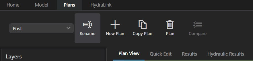
Plan management is accessed from the Plans tab in the ribbon toolbar. The tab contains the following controls:
- Plan dropdown: selects the active plan. The map, data grid, and properties panel update to show that plan’s elements and results.
- Rename renames the active plan inline.
- New Plan asks for a name and creates an empty plan.
- Copy Plan duplicates the active plan, including all elements and connections. After naming the copy you are asked whether the copied elements should be linked to the source plan: answer No for an independent pre/post copy, Yes to keep them in sync.
- The trash-can Plan button (Delete Plan) removes the active plan after asking for confirmation (the project must always have at least one plan).
- Compare: shows a side-by-side comparison of linked elements across plans (enabled after running the solver on multiple plans), with the change from the first plan in cfs and as a percentage. Only linked (shared) elements are compared; the dialog says so if there are none.
Creating a New Plan
- Switch to the Plans tab in the ribbon toolbar.
- Click New Plan and enter a descriptive name (e.g., “Post-Development” or “Alternative B”). Use Rename later if needed.
- Add elements to the plan or link existing elements from other plans.
Switching Between Plans
Use the plan dropdown in the Plans tab to switch between plans. The map view, data grid, and properties panel update to show the active plan’s configuration. Results are computed and stored per plan.
Comparing Results
After running the solver on all plans, click Compare in the Plans tab to view a side-by-side summary of linked elements across plans. The comparison table lists peak outflow from each plan for every storm event, then, for every other plan, the change from the first plan in the plan list (the status line names it) as Δ in cfs and Δ% of the baseline (green = reduction, red = increase). An increase carries a plus sign; a change that rounds to zero at the project’s display precision carries no sign; a storm either plan has no result for, or a percentage of a baseline that prints as zero, shows a dash rather than a number. The same rules print in the report’s Linked Junction Comparison and in the Civil 3D palette’s Design Point Comparison table. Select a row to see the plans’ hydrographs overlaid.
Linked Drawings
A plan can be linked to a Civil 3D drawing, and a project can be fed by more than one of them, since existing and proposed conditions usually live in separate drawings. Each plan reads one drawing; each drawing keeps its own plans, and saving from one never disturbs another’s. The drawing-side workflow, pairing the design points and printing the comparison, is in Existing and Proposed in Two Drawings.
Civil 3D › Drawings in the ribbon opens Linked Drawings, which lists every plan with its drawing, its Civil 3D site, its status and the file it reads:
- Linked means the plan is up to date.
- Changed in Civil 3D: sync means the drawing has been re-exported since this plan last synced.
- File missing means the file the plan reads is no longer there.
- Moved: re-link means a file elsewhere reports the same drawing, so the plan can be pointed at it.
- Not linked means the plan was built in the desktop app.
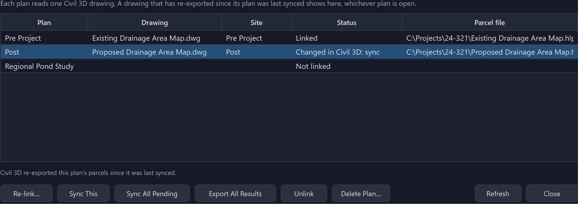
The verbs across the bottom act on the selected row or on the project: Re-link…, Sync This, Sync All Pending (every waiting plan in turn, each against its own drawing), Export All Results (re-publish results for every linked plan; Run All Plans and a save already do this, so the button is for when a drawing reports its results file missing), Unlink, which leaves a plan’s basins with their data but stops them syncing, and Delete Plan…, which deletes the selected plan (any plan, not only the open one) and its elements after the same warning the ribbon’s Delete Plan gives. The plan’s drawing is not touched: its parcels keep their HydraLink properties, and it simply stops being part of the project until it saves into it again.
The sync indicator counts the whole project, not the open plan, because the plan you are not looking at is the one that goes stale, and its tooltip names the plans waiting. Re-link… to a file that reports the same drawing (a rename, or a project copied to another folder) keeps the coordinate system, parcel outlines and site choice; pointing a plan at a genuinely different drawing asks those questions again.
Plans can also reference each other. A detention basin in the proposed plan can take its allowable release from a design point in the existing plan, whichever drawings the two came from. Deleting a plan therefore says what it will break before it does it: the references from other plans, the drawing link, and the design work that no re-sync could rebuild.
Considerations
- Link elements that represent unchanged conditions (off-site areas, existing infrastructure) to avoid data duplication and ensure consistency across scenarios.
- Use separate (non-linked) elements for anything that changes between scenarios, such as on-site basins with different land use or proposed ponds with different configurations.
- Give plans clear, descriptive names so it is easy to identify which scenario each represents.
- Storm events belong to the project and apply to every plan automatically.
- Where existing and proposed conditions are drawn separately, model each in its own drawing and save both into one project. The plans sit side by side and can reference each other, and neither drawing’s save disturbs the other’s work.