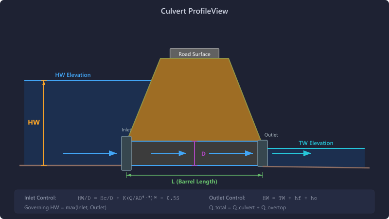
Culvert Element
The Culvert element analyzes the hydraulic capacity of culvert crossings using the FHWA HDS-5 (Hydraulic Design of Highway Culverts) methodology. It evaluates both inlet control and outlet control conditions and reports the governing headwater elevation, capacity, and road overtopping flow.
When to Use
- Evaluating existing or proposed culvert crossings
- Sizing culverts for roadway crossings
- Determining headwater elevation and adequacy for design storms
- Analyzing road overtopping conditions
Barrel Shapes
Two barrel shapes are supported:
- Circular: Defined by diameter (D). Area = π/4 × D². Hydraulic radius R = D/4 (flowing full).
- Box (Rectangular): Defined by width (W) and height (H). Area = W × H. Hydraulic radius R = (W×H) / (2×(W+H)).
Entrance Types
HydraLink includes 11 entrance configurations with pre-calibrated HDS-5 coefficients. Each entrance type has calibrated coefficients K, M, c, Y (for inlet control) and Ke (entrance loss for outlet control).
Circular Culverts
| Entrance Type | Ke | Description |
|---|---|---|
| Square Edge with Headwall | 0.50 | Standard headwall with square-edged entrance |
| Groove End with Headwall | 0.20 | Corrugated metal pipe with groove end in headwall |
| Groove End Projecting | 0.20 | Corrugated metal pipe projecting from fill |
| Beveled Edge | 0.25 | Entrance with beveled edges (33.7° or 45°) |
| Thin Wall Projecting | 0.90 | Thin-wall pipe projecting from embankment |
| Mitered to Slope | 0.70 | Pipe cut to match embankment slope |
Box Culverts
| Entrance Type | Ke | Description |
|---|---|---|
| Box Square Edge | 0.50 | Square-edged box with headwall |
| Box Groove End | 0.20 | Box with groove-end connection to headwall |
| Box Beveled Edge | 0.25 | Box with beveled entrance edges |
| Box Wingwall Flare 30°–75° | 0.40 | Box with wingwalls flared 30° to 75° |
| Box Wingwall Flare 90° or 15° | 0.70 | Box with wingwalls at 90° (parallel) or 15° |
Inlet vs. Outlet Control
Both inlet control and outlet control headwater depths are computed independently; the higher value governs. This follows the HDS-5 dual-analysis approach used by FHWA HY-8.
Inlet Control (HY-8 Polynomial Method)
Inlet control headwater is computed using the FHWA HY-8 fifth-order polynomial equations rather than the traditional HDS-5 K/M two-equation approach. This provides a single continuous curve that smoothly transitions between unsubmerged and submerged conditions without requiring regime interpolation.
Flow parameter:
Headwater depth:
Where:
- poly(X) = A + BX + CX² + DX³ + EX⁴ + FX⁵ — fifth-order polynomial fit to FHWA nomographs
- SR = slope reduction factor (entrance-type dependent; typically −0.5 for conventional entrances, +0.7 for mitered-to-slope)
- S0 = barrel slope (ft/ft)
- D = barrel rise (diameter for circular, height for box)
Each of the 11 entrance types has a unique set of six polynomial coefficients (A–F) and a slope reduction factor SR, sourced from HY-8 v7.7 Appendix A.
Outlet Control (Backwater Analysis)
Outlet control uses a direct-step backwater analysis to compute the water surface profile through the barrel, rather than the simplified single-equation HDS-5 energy method alone. The approach adapts to flow regime:
Mild Slopes (normal depth > critical depth)
A Gradually Varied Flow (GVF) M1 profile is computed from the outlet upstream using the direct-step method. The starting depth at the outlet is max(TW, dc). If the profile reaches the barrel crown, it transitions to full-pipe pressure flow for the remaining upstream length:
Steep Slopes with TW > dc
Both an S2 (supercritical) profile from the inlet and an S1 (subcritical) profile from the outlet are computed. A hydraulic jump forms where the sequent depth of the S2 profile exceeds the S1 depth. The inlet headwater is determined from whichever profile governs at the inlet.
Steep Slopes with TW ≤ dc
Supercritical flow persists throughout the barrel (S2n profile). The simplified HDS-5 energy equation is used:
Where H = (1 + Ke + 29n²L/R4/3) × V²/(2g) and ho = max(TW, dc).
Full-Pipe (Submerged Outlet)
When TW ≥ D (outlet submerged), the full-pipe energy equation is used for the entire barrel length:
Critical Depth
Circular (empirical):
Box:
Road Overtopping
When headwater exceeds the road crest elevation, road overtopping flow is computed. This is a required input on every culvert element.
| Parameter | Units | Description | Default |
|---|---|---|---|
| Road Crest Elevation | ft | Elevation of the road surface at the crossing | Required |
| Road Length | ft | Length of road perpendicular to flow (weir length) | Required |
| Road Width | ft | Width of road in flow direction | Required |
| Weir Coefficient | — | Broad-crested weir coefficient | 2.6 (paved) |
Overtopping discharge:
Where H = headwater elevation − road crest elevation.
Total flow = culvert flow + overtopping flow (when headwater > road crest).
Road overtopping parameters are required on every culvert element. Always verify that the road crest elevation, road length, and road width are set correctly — overtopping flow can be a significant portion of total flow during extreme events.
Manual Flow Mode
The culvert can accept manual flow inputs instead of computing from an upstream hydrograph:
- Enable “Use Manual Flows”
- Enter up to 2 manual flows with custom labels (e.g., “25-yr Pre-Dev”, “100-yr Post-Dev”)
- Select which storm return periods to analyze
Manual flow mode is useful for evaluating culvert capacity without building a full upstream network. This allows quick analysis of specific design flows.
Input Parameters
| Parameter | Units | Description |
|---|---|---|
| Barrel Shape | — | Circular or Box |
| Diameter (circular) | ft | Pipe diameter |
| Width (box) | ft | Box culvert span |
| Height (box) | ft | Box culvert rise |
| Length | ft | Barrel length |
| Slope | % | Barrel slope (max 55% per HY-8) |
| Manning's n | — | Barrel roughness |
| Entrance Type | — | One of 11 types (see Entrance Types above) |
| Number of Barrels | — | Parallel identical barrels |
| Invert Elevation (inlet) | ft | Upstream invert |
| Invert Elevation (outlet) | ft | Downstream invert |
| Tailwater Condition | — | Free Outfall or Specified Elevation |
| Tailwater Elevation | ft | Downstream water surface (if specified) |
Results
| Output | Units | Description |
|---|---|---|
| Headwater Elevation | ft | Water surface elevation upstream of culvert |
| HW/D Ratio | — | Headwater depth / barrel height (key adequacy metric) |
| Control Type | — | Inlet Control or Outlet Control |
| Culvert Discharge | cfs | Flow through the barrel(s) |
| Overtopping Discharge | cfs | Flow over the road (if applicable) |
| Total Discharge | cfs | Culvert + overtopping |
| Outlet Velocity | ft/s | Exit velocity for erosion assessment |
Tips & Best Practices
- HW/D ≤ 1.0 is generally considered adequate for most jurisdictions.
- Some jurisdictions allow HW/D up to 1.2 or 1.5 — check local standards.
- If headwater exceeds the road crest, the culvert is overtopping — evaluate whether this is acceptable for the design storm.
- Use a lower Manning's n for concrete (0.012–0.013) and higher for corrugated metal (0.024–0.027).
- Multiple barrels are modeled as parallel identical barrels sharing the total flow equally.
- Always verify that the road overtopping parameters are set correctly — overtopping flow can be a significant portion of total flow during extreme events.
- The entrance type significantly affects inlet control capacity — beveled and groove-end entrances provide substantially better performance than square-edge.
HY-8 Comparison
HydraLink's culvert engine has been compared against FHWA HY-8 v7.7 across a range of flow conditions, barrel sizes, entrance types, and slope regimes. The following summarizes the key alignments.
Methodology Alignment
| Feature | HY-8 Approach | HydraLink Implementation |
|---|---|---|
| Inlet control | Fifth-order polynomial per entrance type | Same polynomials (HY-8 v7.7 Appendix A coefficients) |
| Outlet control | Direct-step backwater with crown transition | Direct-step backwater with crown transition detection |
| Slope classification | Compare yn to dc | Same (steep when yn < dc) |
| Steep slope outlet control | S2/S1 profiles with hydraulic jump detection | Same dual-profile approach with sequent depth check |
| Maximum slope | 55% (0.55 ft/ft) | 55% enforced by validation |
References
- FHWA (2012). Hydraulic Design of Highway Culverts, HDS-5, Third Edition.
- FHWA (2005). HY-8: Culvert Hydraulic Analysis Program, v7.7. Federal Highway Administration.