Channel Element
The Channel element evaluates open channel capacity using Manning's equation. It computes normal depth, velocity, Froude number, and flow regime for a given design flow and channel geometry. HydraLink supports four channel shapes: Rectangular, Trapezoidal, V-Shape, and User-Defined cross-sections.
When to Use
- Evaluating existing or proposed open channel capacity
- Verifying that a channel can convey the design flow
- Determining normal depth and velocity for erosion assessment
- Checking flow regime (subcritical, critical, or supercritical)
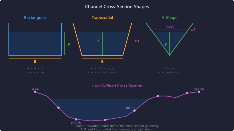
Channel Shapes
Four cross-section geometries are available:
Rectangular
Parameters: Bottom Width (B), depth (y)
- Area: A = B × y
- Top Width: T = B
- Wetted Perimeter: P = B + 2y
Trapezoidal
Parameters: Bottom Width (B), Side Slope (z, H:V), depth (y)
- Area: A = (B + z×y) × y
- Top Width: T = B + 2z×y
- Wetted Perimeter: P = B + 2y × √(1 + z²)
V-Shape
Parameters: Side Slope (z, H:V), depth (y). Bottom width is zero.
- Area: A = z × y²
- Top Width: T = 2z × y
- Wetted Perimeter: P = 2y × √(1 + z²)
User-Defined
Manual station-elevation cross-section editor. Enter paired station (horizontal distance) and elevation points. HydraLink computes area, wetted perimeter, and top width from the geometry at each depth.
Manning's Equation
HydraLink solves Manning's equation in US customary units:
Where:
- V = average velocity (ft/s)
- n = Manning's roughness coefficient
- R = hydraulic radius = A / P (ft)
- S = channel slope (ft/ft)
- Q = discharge (ft³/s)
- A = cross-sectional flow area (ft²)
- P = wetted perimeter (ft)
Normal Depth Solution
For a given design flow Q, HydraLink solves for the depth y that satisfies Manning's equation using a bisection method (range 0.001 to 100 ft). This iterative solution finds the unique normal depth for the specified flow and geometry.
Froude Number & Flow Regime
The Froude number characterizes the flow regime:
Where:
- g = 32.174 ft/s² (gravitational acceleration)
- Dh = hydraulic depth = A / T (ft)
- T = top width of the water surface
Flow Regime Classification
| Froude Number | Flow Regime | Characteristics |
|---|---|---|
| Fr < 1.0 | Subcritical | Slow, deep flow. Controlled by downstream conditions. Most common in design. |
| Fr = 1.0 | Critical | Transitional. Minimum specific energy. Unstable in practice. |
| Fr > 1.0 | Supercritical | Fast, shallow flow. Controlled by upstream conditions. May cause erosion. |
Supercritical flow (Fr > 1.0) can cause erosion and is difficult to control. For most stormwater design, subcritical flow (Fr < 1.0) is preferred. If the Froude number exceeds 1.0, consider flattening the channel slope or increasing roughness.
Input Parameters
| Parameter | Units | Description |
|---|---|---|
| Channel Shape | — | Rectangular, Trapezoidal, V-Shape, or User-Defined |
| Bottom Width | ft | Width of channel bottom (Rectangular, Trapezoidal) |
| Side Slope | H:V | Horizontal to vertical ratio (Trapezoidal, V-Shape) |
| Manning's n | — | Roughness coefficient |
| Slope | % | Channel longitudinal slope |
| Design Flow | cfs | Flow rate to evaluate (from upstream element or manual) |
| Station-Elevation Points | ft, ft | Cross-section geometry (User-Defined only) |
Common Manning's n Values
| Material | Manning's n |
|---|---|
| Concrete (finished) | 0.012–0.013 |
| Concrete (unfinished) | 0.014–0.017 |
| Riprap | 0.030–0.040 |
| Earth (clean) | 0.022–0.030 |
| Earth (with vegetation) | 0.030–0.050 |
| Natural stream (clean) | 0.030–0.040 |
| Natural stream (brush) | 0.050–0.100 |
| Grass-lined | 0.030–0.050 |
Results
| Output | Units | Description |
|---|---|---|
| Normal Depth | ft | Depth of uniform flow at the design discharge |
| Velocity | ft/s | Average flow velocity |
| Flow Area | ft² | Cross-sectional area of flow |
| Wetted Perimeter | ft | Length of channel boundary in contact with water |
| Hydraulic Radius | ft | A / P |
| Top Width | ft | Width of water surface |
| Froude Number | — | Dimensionless flow regime indicator |
| Flow Regime | — | Subcritical, Critical, or Supercritical |
| Channel Capacity | cfs | Maximum flow the channel can convey at full depth |
Tips & Best Practices
- For most stormwater design, subcritical flow (Fr < 1) is preferred. Supercritical flow can cause erosion and is difficult to control.
- Channel slopes steeper than about 2% often produce supercritical flow — verify the Froude number.
- Use the User-Defined cross-section for irregular natural channels surveyed from field data.
- Manning's n is the most uncertain parameter in open channel analysis. When in doubt, use a higher value (more conservative for capacity, less conservative for velocity).
- Verify that the computed velocity is within acceptable limits for the channel lining material. Concrete can handle > 10 ft/s; grass-lined channels typically limit to 4–6 ft/s.
References
- Chow, V.T. (1959). Open-Channel Hydraulics. McGraw-Hill.