Pond Element
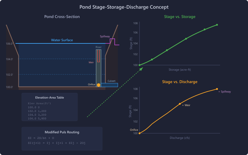
The Pond element models detention and retention facilities that store and attenuate stormwater runoff. Ponds use elevation-area tables to define their storage geometry and can route inflow hydrographs using the Modified Puls method or size detention using the Modified Rational Method (MRM).
When to Use
- Detention pond design and analysis
- Retention basin modeling
- Any facility that temporarily stores runoff and releases it at a controlled rate
- MRM detention sizing for small watershed studies
Storage Modes
Two storage modes are available:
Stage-Storage Table (Surface Ponds)
Define the pond geometry using an elevation-area table. HydraLink computes the volume between each elevation increment using one of two methods:
-
Conic Method (default):
V = h/3 × (A1 + A2 + √(A1 × A2))— accurate for ponds with sloping sides. -
Average End Area Method:
V = h/2 × (A1 + A2)— simpler, slightly overestimates volume.
Example Elevation-Area Table
| Elevation (ft) | Area (ft²) |
|---|---|
| 100.0 | 0 |
| 101.0 | 500 |
| 102.0 | 1,200 |
| 103.0 | 2,100 |
| 104.0 | 3,200 |
| 105.0 | 4,500 |
Outlet Structures
Ponds use a combination of outlet structures to control the outflow at different stages. The total outflow at any stage is the sum of discharge from all active outlet structures at that stage.
1. Primary Culvert
A culvert barrel at the base of the pond. Analyzed using the same HDS-5 methodology as the standalone Culvert element. Configure barrel shape, dimensions, entrance type, length, slope, and Manning's n.
2. Primary Riser
A vertical riser structure with multiple outlet openings at different elevations:
Orifices
Circular or rectangular openings.
- Circular:
A = π/4 × D² - Rectangular:
A = W × H
Weirs
Horizontal openings along the riser.
Defined by crest elevation, width, and weir coefficient.
Top Overflow
When water overtops the riser, the riser perimeter acts as a weir. Effective width = riser perimeter minus the sum of all weir widths.
3. Secondary Culvert (Optional)
An additional culvert for higher-stage discharge, configured the same as the primary culvert.
4. Spillway
Emergency overflow weir with four types:
- Sharp-Crested Rectangular
- Broad-Crested Rectangular
- V-Notch (90°)
- Cipolletti (trapezoidal)
5. Exfiltration / Infiltration
Models water leaving the pond through bottom and side infiltration into the surrounding soil using Darcy’s law:
Where K = saturated hydraulic conductivity (in/hr), A = infiltration area, and SF = safety factor.
- Soil Type — select from 11 Green-Ampt soil texture presets (Sand through Clay) to auto-fill the hydraulic conductivity, or choose Custom to enter a value directly.
- Safety Factor — reduction factor (0–1, default 0.5) to account for long-term clogging and compaction.
- Bottom Infiltration — uses the pond-bottom area from the elevation-area table, or a custom area override.
- Side-Wall Infiltration — optional; estimates infiltration through the pond side walls from contour perimeters.
6. User-Defined Stage-Discharge Curve
For non-standard outlet configurations, you can enter a custom elevation-discharge table directly. This overrides the computed stage-discharge from other outlet structures.
- Enter elevation (ft) and discharge (cfs) pairs manually or import from CSV.
- Useful for modeling proprietary outlet devices, vortex valves, or complex multi-stage structures that cannot be represented by the built-in outlet types.
Modified Puls Routing
The primary routing method for ponds. At each time step:
-
Compute the storage indication value:
SIj+1 = Ij + Ij+1 + (SIj − 2Oj) - Interpolate outflow O and storage S from the stage-storage-discharge relationship.
- Track stage, storage, and outflow over the full hydrograph.
The stage-storage-discharge table is computed internally by evaluating all outlet structures at each elevation in the storage table. See the Pond Routing methodology page for full details.
MRM Detention Sizing
When upstream basins use the Modified Rational Method, the pond can perform simplified detention sizing:
Standard Method
Iterates storm durations from Tc to 1440 minutes in 1-minute steps. Iteration stops early once the required storage has been decreasing for 20 consecutive steps past the peak. For each duration, computes:
Required storage = Vin − Vout. Reports the critical duration that maximizes required storage.
Regional IDF Table Method
Uses county- or city-specific coefficients (a, b factors) from the NCTCOG iSWM program (17 DFW-area Texas counties) or the Atlanta Regional Commission Georgia Stormwater Management Manual (16 Georgia cities).
Basin Roles
Basin roles control how each upstream basin participates in detention sizing:
- Design Area
- Post-development area detained by the pond — its C and area contribute to the composite inflow calculation.
- Target
- Pre-development reference — its peak flow defines the allowable release rate from the pond.
- Bypass
- Flow from the site that does not enter the detention pond. Bypass flow reduces the allowable release from the pond, increasing required detention.
- Pass-Through
- Off-site flow that enters and exits the pond but is not detained. The outfall structure must be sized to convey pass-through flow in addition to the allowable detained release.
Input Parameters Summary
| Parameter | Units | Description |
|---|---|---|
| Storage Mode | — | Stage-Storage Table (elevation-area) |
| Elevation-Area Table | ft, ft² | Pond geometry (Stage-Storage mode) |
| Volume Method | — | Conic or Average End Area |
| Initial Elevation | ft | Starting water surface elevation |
| Tailwater Condition | — | Free Outfall or Specified Elevation |
| Tailwater Elevation | ft | Downstream water surface (if specified) |
| Primary Culvert | various | Barrel shape, dimensions, entrance type, etc. |
| Riser | various | Orifice and weir definitions |
| Secondary Culvert | various | Optional additional barrel |
| Spillway | various | Emergency overflow weir type and geometry |
| Exfiltration | various | Soil type, hydraulic conductivity, safety factor, bottom/side infiltration |
| User-Defined Stage-Discharge | ft, cfs | Custom elevation-discharge table for non-standard outlets |
Results
| Output | Units | Description |
|---|---|---|
| Peak Inflow | cfs | Maximum inflow rate |
| Peak Outflow | cfs | Maximum outflow rate |
| Peak Stage | ft | Maximum water surface elevation |
| Peak Storage | acre-ft | Maximum stored volume |
| Time to Peak Stage | hours | Time of maximum water surface |
| Stage-Storage-Discharge Table | ft, acre-ft, cfs | Computed relationship at all stages |
| Outflow Hydrograph | cfs vs. time | Full routed outflow |
| Stage Hydrograph | ft vs. time | Water surface elevation over time |
Tips & Best Practices
- Always verify the stage-storage-discharge table before running — inspect the computed outflow at each elevation to ensure outlet structures are behaving as expected.
- Use the Conic volume method for natural ponds with irregular grading. Average End Area is acceptable for rectangular facilities.
- Place the spillway crest at or below the top of the storage table to ensure emergency overflow is modeled.
- For MRM sizing, ensure all upstream basins have their roles properly assigned.
- When comparing Modified Puls routing to MRM sizing, the Puls method is more accurate but requires a fully defined outlet structure. MRM provides a quick volumetric estimate.
- Ensure the elevation-area table starts at the invert (lowest point) of the pond.
Always verify the stage-storage-discharge table before running a simulation. Inspect the computed outflow at each elevation to confirm that outlet structures are configured correctly and producing expected discharge values.
If the spillway crest is above the top of the storage table, emergency overflow will not be modeled and the pond may show unrealistic results at high stages.