Civil 3D Integration
Overview
HydraLink ships a companion add-in for Autodesk Civil 3D that lets you run drainage calculations directly on Civil 3D parcels and hand the completed model to HydraLink desktop with a single save. Your parcel data stays in the drawing throughout design; when you’re ready to solve, HydraLink desktop builds a project from it, and once you solve and save, the results are ready to pull back into the drawing with one command.
Setup
Run the HLSETUP command once per drawing to add HydraLink properties to your
Civil 3D parcels. If you skip this step, the properties are added the first time the
calculator writes to a parcel. Running HLSETUP up front also creates the
flow-result fields for your selected storms, so parcel labels and tables can reference them
before anything is solved.
The ribbon carries one button, HydraLink, which opens the calculator palette.
Everything else, such as importing results and drafting tables, is inside the palette; the
HL commands below remain available at the command line.
The Calculator Palette (HLCALC)
HLCALC opens a dockable palette for building and reviewing your
drainage model without leaving Civil 3D. Its five tabs are Storms, Basins, Junctions,
MRM, and Ponds, in the order the work usually happens.
Palette Toolbar
Across the top of the palette: File ▾ (Save .hyd, Import Results, Export Parcels), Output… (draft the palette’s tables and pond charts into the drawing and keep them current; see below), Settings (input defaults, overlays and plan display, per user), and the Active plan selector with Plans… for linking design conditions to Civil 3D sites.
Under the drawing name, the header shows the project this drawing is part of: a green dot and the .hyd file’s name when it is linked, an amber triangle when the recorded project file can no longer be found (use File › Open .hyd… to link it again), or No project when the drawing has never been saved into or opened from one. A drawing can hold basins, junctions and storms without belonging to a project, so check this line when you pick up a drawing someone else started. Hover it for the full path.
Output
Output… opens one dialog for everything the palette draws into the
drawing. The top half lists what can be drafted right now: the basin, junction, pond,
culvert and MRM detention tables, the designed pond’s stage-storage-discharge table,
design summary and rating curve (drawn or as an image), and the results summary from a
.hlresults file. Each carries a note on what it would hold, or why it cannot be
drafted yet. Check the ones you want and choose how they are placed: Pick a point for
each prompts for every output in turn, while Stack from one pick asks for a single
insertion point and lays the outputs out top-down in the order listed, with charts sized to
the tables above them.
The bottom half lists everything already drafted and whether it still matches the palette’s numbers; a badge on the Output button counts the outputs that no longer do. Update Stale re-draws them in place (same position, space, layer and style), Update Selected re-draws the highlighted ones whatever they read (the design point comparison reads another drawing’s file, so the palette cannot check it on its own), and Remove Selected stops tracking one without touching the drawing. The iteration tables drafted from the MRM dialog are tracked here too.
Split basin table every … rows, on the settings line of the same dialog, is how long the basin flow table may get before it splits into numbered parts (“1 OF 3”), each a complete table that is tracked and updated on its own. Leave it blank for one table however long. Only the basin table splits; pond, MRM and rating-curve outputs always stay whole.
Table Settings…, on the same line, holds everything else stored in the drawing: which of the analyzed storms the tables print (a storm left unchecked is still analyzed, exported and imported, it just prints no column), how the design point comparison is cut (the change stated in cfs or as a percentage, which condition is the baseline, and which conditions print), the heading of every table (blank prints the built-in one; type your own to replace it), and display precision.
Storms Tab
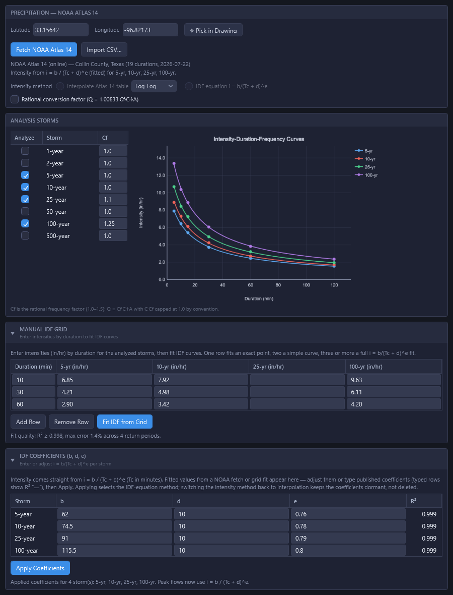
Pick your design return periods, then supply rainfall data by fetching NOAA Atlas 14
precipitation for a location (or by picking a point on the drawing), importing a CSV, or
entering values manually. An IDF curve chart and b/d/e coefficient entry are available
(TxDOT convention i = b/(Tc+d)^e), and you choose which intensity method the
calculator should use.
Basins Tab
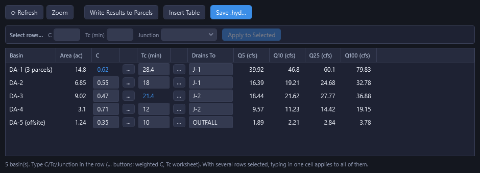
One row per basin, showing area, C, Tc, Drains To, and computed peak flow (Q) for each return period, updated live as you edit parcels. Selecting a row highlights the corresponding parcel in the drawing. A bulk-apply bar lets you edit a parameter across many selected basins at once.
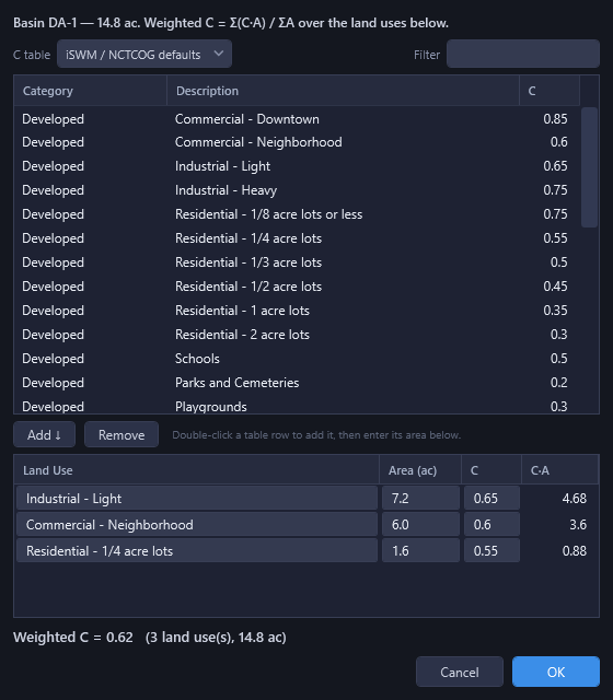
- The Weighted C worksheet builds an area-weighted composite runoff coefficient from a land-use breakdown, drawing on built-in municipal C tables or ones you save yourself. Add ↓ puts the highlighted land use in the breakdown with an empty area for you to type; Fill gives the selected entry whatever area is still unassigned, so a basin covered by a single land use is Add then Fill. The unassigned figure is shown beside the buttons, and an area typed larger than what is left is reduced to it, so the breakdown cannot overshoot the basin. When nothing is left to reduce it to, the figure you typed stays on screen and the dialog names the land use that has to give the area back before you can save. Type what the unassigned line says is left (3 when it reads 3 ac) and the entry takes the exact remainder, so the breakdown adds up to the parcel without typing its area to the last digit; the line and the grid use your display precision for drainage area (two decimals unless you change it).
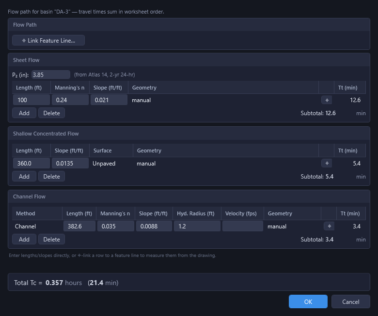
- The Tc worksheet is a TR-55 style sheet flow / shallow concentrated flow / channel segment builder that can take its lengths and slopes from a feature line in the drawing.
- Connection markers mark the inlet a basin actually discharges at; Suggest Markers proposes them from the plan’s surface.
- Basin Links tie the same drainage area across design conditions so C and Tc stay identical.
Junctions Tab
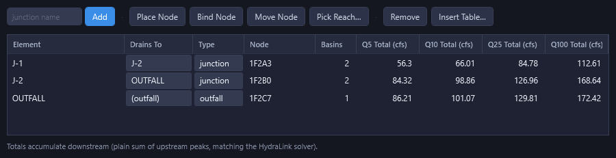
Define what drains where, from basins to junctions and from junctions to downstream junctions, and place junctions directly in the drawing with a click; each one gets a symbol at the picked point. Each junction shows total accumulated flow per return period. Selecting a junction highlights its watershed and flow lines in the drawing, and the Basins tab can zoom to a basin’s parcels. Both are optional overlays you can switch off in Settings. A junction that is the same design point as one in another drawing carries a ⇄ mark; Pair Across Drawings… is where that is set; see Existing and Proposed in Two Drawings.
MRM Tab
Size detention with the Modified Rational Method before a pond is ever drawn. Click Add… to place an MRM element in the drawing, then use Design… to say whose runoff it holds: tick the junctions or individual basins that make up the design area, and the ones whose existing-conditions flow sets the allowable release (target and bypass). These are the same four roles the desktop’s MRM basin uses. A row carries one role: ticking another column moves it there. A ticked junction selects everything draining through it, and goes on standing for it as the drawing changes. A basin added to that junction later is carried too, so the design area keeps matching the model instead of freezing at the moment you ticked. To except one basin, tick it in another column: the one basin of a pond’s drainage area that actually bypasses the pond is a single click on that basin’s Bypass box, and the junction stops carrying it. Clearing a carried basin outright, without giving it another role, breaks that junction up into its basins. That is useful, but it then stops picking up new ones, and its box reads part-filled to say so. Clicking a part-filled junction ticks it again and takes its whole drainage area back. A basin belongs to one MRM element, whatever its role. A row another element holds says which in its tooltip, and ticking it asks before moving it; Yes takes it out of that element, breaking up a junction there that carried it. The MRM tab names any basin two elements already hold, and the desktop will not run the project until it is taken out of all but one. The pond this element sizes can be ticked as Design but not as Target, Bypass or Pass-thru: its flow is the inflow being detained, so the release is read at a point downstream of it. Shift- or Ctrl-click selects several rows, and one tick then applies to all of them. If the drainage area hasn’t been modeled yet, type the area, C, and Tc directly instead. The tab lists what each element is connected to and the storage required for every sized storm, the governing one marked; the dialog shows the full per-storm sizing, with the pre-project Target column tinted so it reads apart from the post-project flows, and beneath it the sizing detail for the storm you click: the design-storm hydrograph and the duration sweep behind its volume. Allowable release from chooses where the release comes from: the ticked model elements (target minus bypass), or flows you type per storm (Manual). Either way a storm the chosen source sets no positive release for falls back to its typed allowable Qa, used exactly as entered. Insert Iteration Tables… drafts the duration sweep behind each volume, the arithmetic a reviewer asks to see, as one table per design storm. Every sized storm is selected to begin with; narrow the selection in the required-storage grid to draft fewer. A storm hidden from this drawing’s tables is left out unless you select it yourself. An MRM element is a calculation, not a structure. It holds what drains to it and passes nothing downstream until you link it to a pond, which is what carries the required volume onto the Ponds tab. The link is the Pond column on the tab or the Sizes pond box at the top of the dialog; either one sets the same link. A pond takes one MRM element, so a pond another element already sizes is not offered; let one element’s design area cover everything that pond detains. Ticking the pond node itself as the design area is the simplest way. Anything that drains to the pond from outside the design area (and is not selected as pass-through) is named on the MRM tab, the Ponds tab verdict does not pass, and Save .hyd exports the sizing on its own instead of onto the pond until you add it to the design area or drain it elsewhere. A sized pond draining into another sized pond is treated the same way, since ponds in series need a unit hydrograph (SCS) network: the lower pond is exported without its sizing.
When the existing condition is in another drawing, the release can still come from it. Two buttons below the role grid add an element from another plan of the same project as a row of that grid, ticked as Target:
- Basin in another drawing… for a Rational-method basin. Its flow is computed here from the area, C and Tc the project records for it, so the other plan need not have been solved, and an edit to that basin over there resizes this pond the next time this drawing re-reads the project (File ▸ Open .hyd…). It can set the release and nothing else, so its Design and Pass-thru boxes are disabled.
- Junction or pond in another drawing… for a junction total or a sized
pond’s release, carrying the flows that plan published at its last solve. A
pond offers a flow only once it has been sized. Because these numbers are copied, the dialog
warns when the source has been solved again, when its flows have changed, or when its file
cannot be found; Refresh all takes the new numbers together, and until you
press it the pond stays sized on what you copied. From another project
file… does the same for a flow out of a previous job’s
.hyd.
Either kind behaves like any other row: make it a bypass, add a second one, put a local junction
beside it, untick it to remove it. Saving the .hyd carries a basin as a reference
and a copied release as per-storm numbers, and says so; a desktop solve reaches the same release
either way.

Ponds Tab
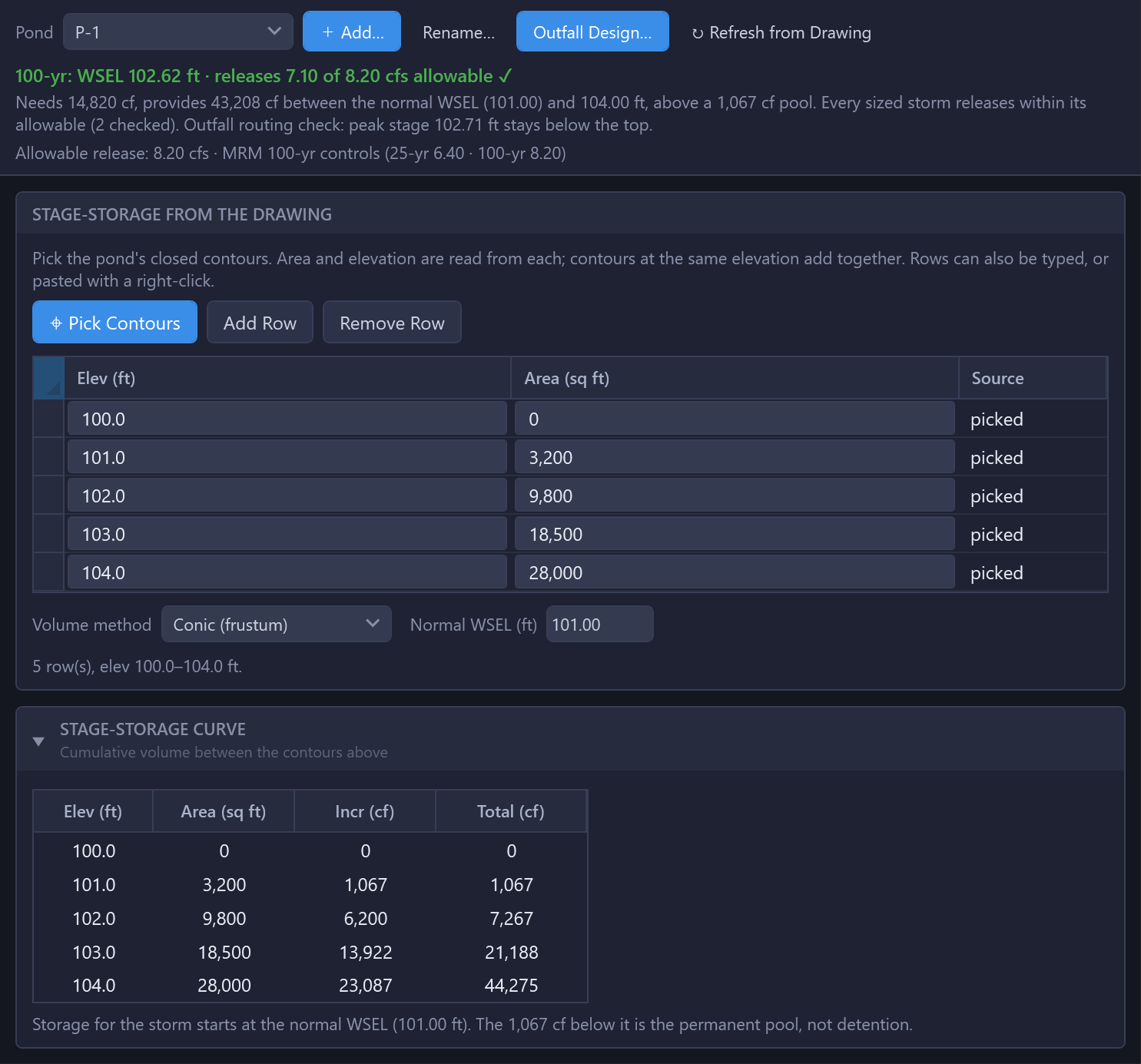
Design the pond that holds the required volume. Pick the closed contours that bound the pond and HydraLink reads each one’s elevation and area straight from the drawing to build the stage-storage table, so nothing is transcribed. Rows can also be typed, or pasted from a spreadsheet with a right-click on the grid. Rename… beside Add… renames the pond; its block, its basins’ labels and any cross-drawing pairing follow. Delete removes the pond, its block and its basins’ labels in one step; Ctrl+Z in the drawing brings it back with its design. The tab reports whether the storage provided meets the linked MRM element’s requirement and where the water surface lands, lists the allowable release for every storm the element sized. The release is checked at every sized storm, not just the one that governs the storage: the outlet has to meet each storm’s own allowable at that storm’s required volume, and the verdict names any that it does not.
A wet pond holds a permanent pool. Type its elevation in Normal WSEL (ft), beside the volume method; leave it blank for a pond that starts the storm empty. Storage and the rating curve then start at the pool: the water below it is there before the storm arrives, so it is not detention. The verdict gives the storage range from the pool up and the volume the pool holds, and the line under the stage-storage curve says the same. Every outlet opening must sit at or above the pool (equal is fine), a primary culvert below it needs a riser, a typed rating curve must release 0 cfs there, and a pond with a pool cannot also exfiltrate. Each conflict is listed under the pond as soon as it is typed, and Outfall Design… refuses OK until it is fixed. The rules are the desktop’s, in Pond.
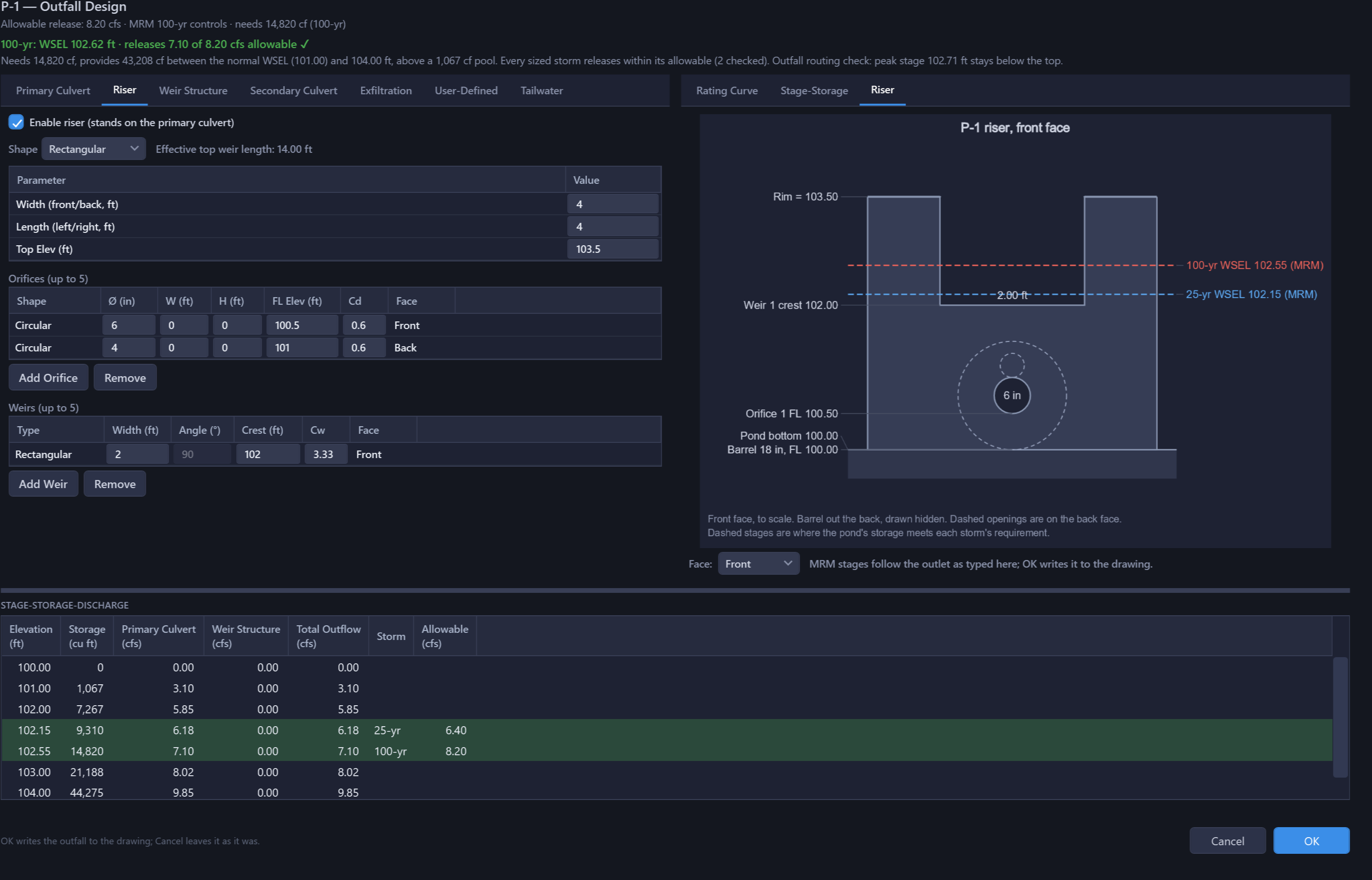
Outfall Design…, beside Add…, opens the outlet structures in the same layout as the desktop Pond dialog: one tab each for the primary culvert, riser, weir structure (its weirs include any emergency spillway), secondary culvert, exfiltration, tailwater, and a typed rating curve that can stand in for the structures, with the rating charts beside them and the stage-storage-discharge table below. Every storm the linked MRM element sized lands on that table as a tinted row at its required volume, showing the stage the pond reaches and the release the outlet gives there against the allowable. Sizing the outlet is then a matter of changing the structure until every tinted row reads OK, with the rating curve beside it showing why. OK writes the outfall to the drawing; Cancel leaves it as it was. OK also checks every opening against the pond: a riser top above the highest contour, an orifice or riser weir above the riser top, or a weir crest above the pond top is refused, with the reason on the status line; see Outlet Elevations.
The Riser pane beside the rating charts draws the riser one wall at a time, the way the structure detail on the plans does: the wall to scale, the weir notches and orifices cut out of the face you pick (Front, Right, Back or Left), the far wall’s openings and the outlet barrel dashed where they are hidden, and a label ladder with every rim, crest, flowline and invert elevation. Each storm the linked MRM element sized crosses it as a dashed water surface at the stage where the pond’s storage meets that storm’s requirement, the same stage the Ponds tab reports; the lines follow the outlet as you type it. A pond with a normal WSEL also gets a solid line at the pool, labelled Normal WSEL. Every orifice and weir on the Riser tab has a Face column saying which wall it is cut into: Front and Back are the riser’s Width, Left and Right its Length, and the barrel always leaves through the Back. Openings side by side at the same elevation may not total more than their wall is wide (openings one above the other do not add up); the sentence appears under the table while you type and OK is refused until an opening is moved to another face or elevation. An opening the drawing cannot place clear of the others on its wall is only a warning. Faces change no flow. The rules are the desktop’s, in Faces.
One-Step Handoff to Desktop
When your basin and junction network is ready, choose File › Save .hyd on the palette. The first time, it asks where to put the project file; after that the drawing remembers its project and saves straight into it, reporting the file it updated in the status line. Save .hyd As… is for deliberately writing a different file, and re-points the drawing at it. The file is a complete HydraLink project: one plan per Civil 3D site, with basins and junctions positioned geographically and parcel boundaries shown on the desktop map. Open it in HydraLink desktop and run the solver as usual.
Saving into a project that already exists keeps other drawings’ plans, anything created in the desktop app, and the edits you made in HydraLink to this drawing’s own plan. If the drawing and the desktop both changed the same value, the drawing’s value is saved and the status line names both, so check it after saving. Geometry taken from the drawing, such as parcel areas and where elements sit, always follows the drawing. You are asked before a save would lose something, and the prompt says what.
File › Open .hyd… reads those desktop edits back into the drawing where it has a place for them: C and Tc onto the parcels, a basin’s junction, a junction’s downstream edge, a pond’s design. What the drawing cannot hold (a rename, a Tc worksheet edited on the desktop, MRM settings) is listed as kept in the project file only, and it survives the next save from here all the same.
Existing and Proposed in Two Drawings
Existing and proposed conditions usually live in separate drawings. One HydraLink project holds
both: each drawing keeps its own plan in the same .hyd, the design points that are
the same point in both conditions are paired, and the comparison prints in the drawing and in
the desktop report. The order that works:
- Model the existing drawing first. Storms, basins and junctions as usual, then File › Save .hyd. The first save asks where to put the project file; give it the job’s name rather than the drawing’s.
- In the proposed drawing, open that project. File › Open .hyd… takes the project’s storms and rainfall, so both conditions are sized on the same rain, and lets this drawing see the existing plan. Model the proposed condition and Save .hyd into the same file: the existing plan is kept and this drawing’s plan is added beside it.
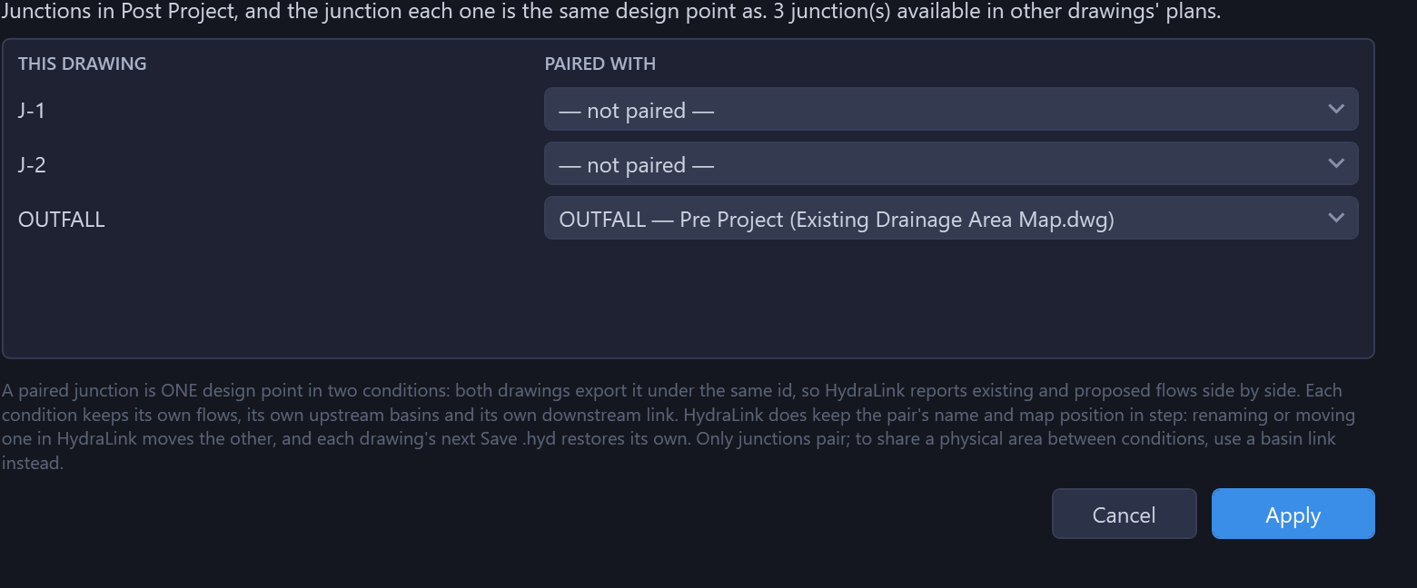
- Pair the design points. On the Junctions tab, Pair Across Drawings… lists this condition’s junctions; beside each, choose the junction in the other drawing that is the same point on the ground, such as an existing J-1 and a proposed J-1. Paired junctions carry a ⇄ mark on the tab. A pairing made in one drawing reaches the other the next time it opens the project.
- Size detention against the existing flows. In the MRM dialog, Basin in another drawing… or Junction or pond in another drawing… adds the existing plan’s element as the Target row, so the allowable release comes from the other drawing without retyping it; see the MRM Tab above.
- Print the comparison. Output… › Design Point Comparison drafts one table: for each paired junction, this condition’s flow, the other’s, and the change, per storm. The other condition’s flows are the ones its drawing last published, so a row saying the other drawing has not published yet means save from that drawing (or solve and save in the desktop) and draft again. Table Settings… chooses whether the change prints in cfs or as a percentage and which condition is the baseline.
- Solve in the desktop. Open the
.hydin HydraLink, Run All Plans, and save. Results are published for every plan, so each drawing’s File › Import Results… brings its own back, and the report’s comparison sheet shows the paired junctions side by side.
Worth knowing once two drawings share a project:
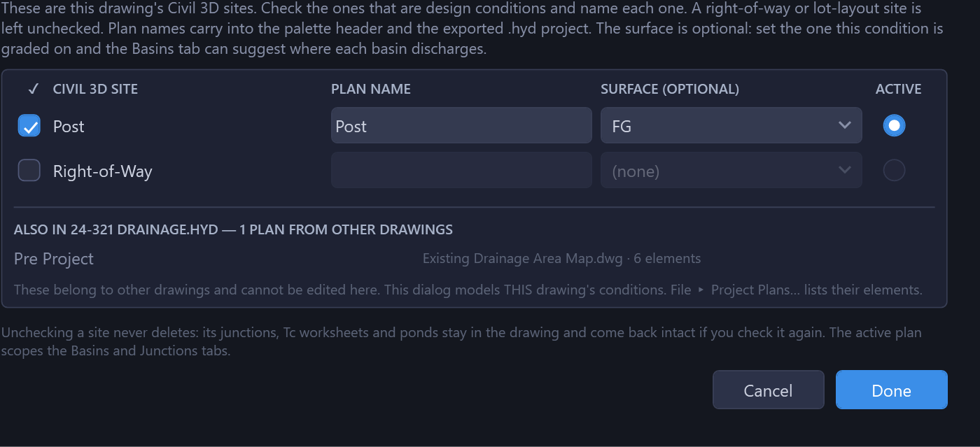
- Plans… shows the whole project. Its top half is this drawing’s
Civil 3D sites; below them, read-only, are the plans that belong to other drawings, each
with the drawing it came from. If the existing plan seems to be missing after Open .hyd,
look there. It can be seen from this drawing but not edited. File ›
Project Plans… lists their elements.
- Only junctions pair. A pairing says “the same design point” and leaves each condition’s inputs alone. A basin that is the same ground in both conditions is a Basin Link instead (Basins tab), which keeps its C and Tc identical. A paired junction that later becomes a pond or an MRM element is refused, with the reason.
- Storms are shared. Whichever drawing edited the storms most recently sets them for the project, and the save says which way it went. Set them once, in the first drawing, and leave the second drawing’s Storms tab alone.
- Desktop edits to a drawing’s plan are kept. Correct a C, design a pond or add a culvert in HydraLink, and the next Save .hyd from that drawing keeps it; Open .hyd in that drawing pulls what it can (C, Tc, connections, the pond design) back onto the parcels and nodes. If the desktop has the project open while you save from Civil 3D, it asks before saving over your changes, so reopen it there first.
- Renaming or moving a drawing changes nothing. The plan follows the drawing, not its file name. Copying a drawing (Save As, or a copy in Explorer) asks once whether the copy is the same drawing under a new name or a new drawing; the default, a new drawing, leaves the original’s plan alone.
- Removing a plan. File › Remove Plans from
Project… takes the ticked plans out of the
.hyd, this drawing’s or another’s. The other drawing keeps its parcel data and rejoins the project the next time it saves into it. The desktop can do the same from Linked Drawings, which also shows every plan with its drawing and whether it is up to date.
Results Back to CAD
After solving and saving in the desktop app, the results are picked up back in the drawing. In a project with several drawings, Run All Plans and a save publish results for every plan, so each drawing imports its own:
- File › Import Results… (or
HLIMPORT) writes the computed flows and intensities to the parcel properties. - Output… › Results Summary Table (or
HLTABLE) places a results summary table in the drawing: one row per junction, pond, culvert, and channel, with the peak flow for each design storm.
While the palette is open it watches the results file and tells you in its status line when HydraLink has published a new solve; File › Import Results… brings it in.
Results carry the drawing they were solved from, and an import into a different one is stopped with a question before anything is written. Parcels are matched individually, so results from the wrong drawing would land on unrelated parcels. Answering no writes nothing. Importing a drawing’s own results after it has been renamed raises nothing at all.
Staying in Sync
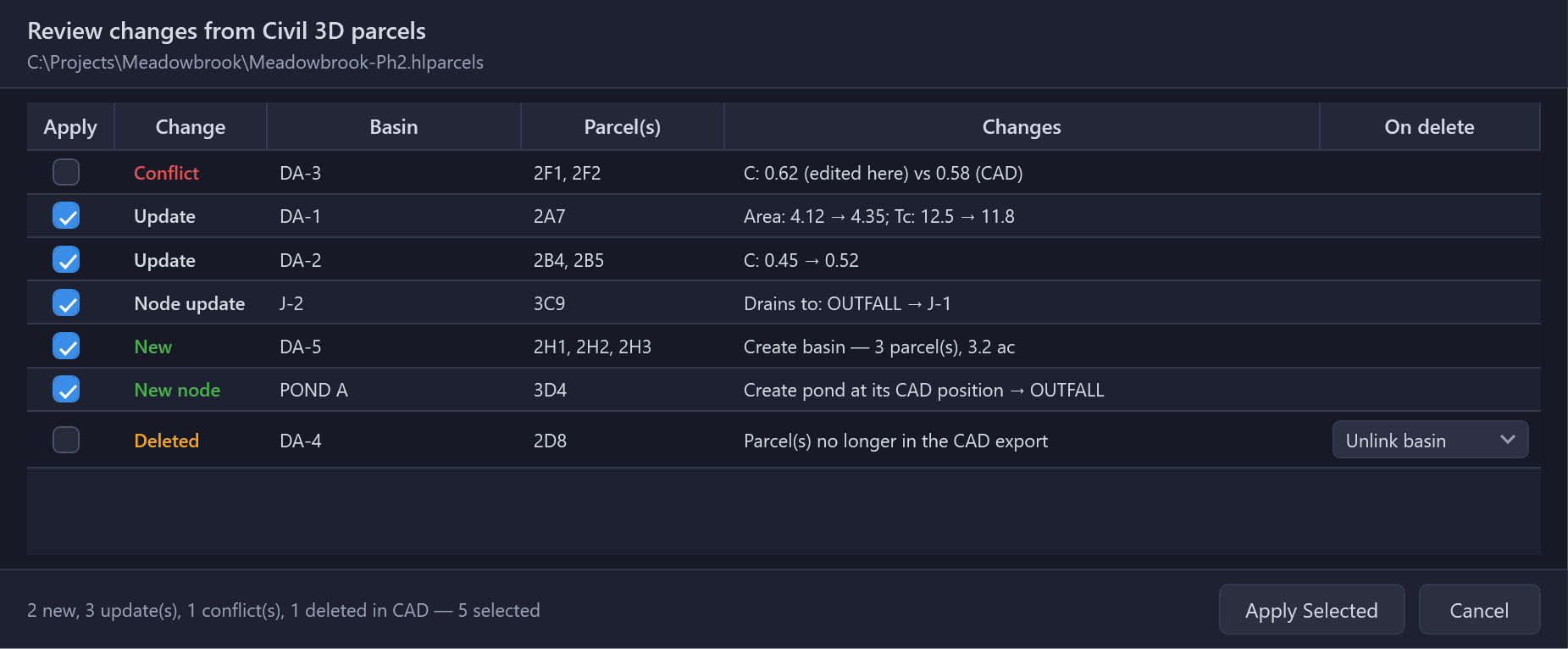
If the drawing changes after handoff, whether areas are adjusted, parameters edited, or new parcels added, the desktop app shows a sync preview of exactly what changed and lets you accept or skip each change individually. It never silently overwrites your design data. A basin’s area is the one exception: it always comes from its parcels, so every sync takes the drawing’s area, even for a basin whose other changes you skip, and the Area of a basin linked to parcels cannot be typed in the desktop app. When the drawing’s parcel file changes, the desktop status bar tells you a sync is waiting, so nothing is out of date without your knowledge.
Command Reference
| Command | Description |
|---|---|
HLSETUP | Adds HydraLink parcel properties to the current drawing. |
HLCALC | Opens the dockable calculator palette (Storms, Basins, Junctions, MRM, Ponds). |
HLIMPORT | Writes computed results from a solved HydraLink project back to parcel properties. |
HLTABLE | Places a network results summary table (one row per junction, pond, culvert, or channel; peak flow per design storm) from a solved project. |
HLEXPORT | Exports parcel data manually; normally not needed, since Save .hyd handles this. |
Requires Civil 3D 2025 or newer. The add-in is included with the HydraLink installer, so no separate download is required.