Drawing Tools
Studio is a rendering tool, not a drafting package; geometry belongs in CAD. But presentation drawings always need a few things the sheet does not have: a bed outline to color, a circle around an area of interest, a rectangle behind a legend. The DRAW tab covers that.
Everything drawn here goes on the currently selected layer and takes that layer's style, so select the layer you want first, or add a new one with the + button in the scene tree.
The tool in use stays lit on the DRAW tab. Over the drawing the pointer becomes a crosshair
(a text cursor for Text), and the status bar names the tool and says what it wants next.
Rectangle, Circle, Text, Leader and Path go back to Select once their object is placed;
Paint stays on until you end it. To put a tool down, press Esc or click its name
in the status bar: Cancel drops a shape still being drawn, and
Done ends Paint.
Select
The default mode, and where Esc returns you from any other tool. See
Canvas & Selection.
Path
Draws an open or closed path of straight and arc segments.
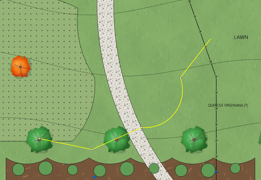
- Click to place each point.
- Alt+drag after at least two points to bend the previous segment into an arc.
- Backspace or
Ctrl+Zremoves the last point placed. - Right-click finishes the path. Ending near the start point closes it into a shape, which is what you want for anything that will be filled.
- Esc abandons it.
Closed paths take fills, textures, gradients and materials. Open paths take stroke styling only.
Editing a path afterwards
Right-click a path and choose Edit Path. Vertices become draggable handles and the EDIT PATH ribbon tab appears:
- Step through segments with the arrow buttons; the label shows which segment of how many.
- Type exact start and end coordinates.
- Read the segment's length, and set an arc's bulge.
- To Arc converts a line segment; To Line straightens an arc.
While an arc is being edited its center crosshair, radius lines, tangents and PI point are
drawn as aids. Dragging a vertex shared by two arcs adjusts the neighbor so the curves stay
tangent. Esc leaves path-edit mode.
Rectangle
Drag a corner to corner rectangle. It is a closed shape like any other, so it fills, takes a texture, and can be edited as a path afterwards.
Circle
Drag from the center outward. Circles have their own radius handles when selected and no rotation handle.
Text and Leader
Both are type-to-create: the object only exists once you commit non-empty text. See Text & Leaders.
Paint
Fills an area from the linework around it: click inside a closed area of the drawing and Studio traces its outline from the CAD lines themselves, arcs and all, as a closed path on the layer selected in the tree (or on a Painted Areas layer when none is). Rest the pointer for a moment to see the area before you click. Hidden layers, and layers faded by an isolation, do not bound the area, so turn off a line you do not want splitting a surface (a floodplain limit through a lawn, say) before you paint.
Join, next to Paint on the DRAW tab and on by default, merges each new area
with the areas it touches on the same layer, so a lawn a line crosses paints as one surface
with no seam. The preview outlines, dashed, the areas a click will join, and a click inside
an area already painted on that layer just selects it. With Join off every click paints an
area of its own, and Shift+click joins. Areas on a locked layer are never joined.
Image, North Arrow, Scale Bar
Image inserts a raster file; see Symbols & Images. North Arrow and Scale Bar insert parametric plan objects; see North Arrow & Scale Bar.
Merging Paths
Several open paths that meet end to end can be joined into one compound object: select them all, right-click and choose Merge Paths. The merged object appears in the scene tree with its components indented beneath it, and styling applies to the parent, so a bed edge assembled from six CAD polylines becomes one thing to color.
Rules the merge enforces:
- All selections must be open paths with at least two points, not closed shapes.
- They must all belong to the same group or viewport.
- They must form a connected chain: shared endpoints, no branches.
Components can still be selected individually inside the merge. Deleting an end component trims the path; deleting a middle one asks whether to split the merge or delete the whole thing. A two-component merge that loses one component dissolves back to a standalone shape. Unmerge on the right-click menu breaks it apart again. All of it is undoable.
Merging Areas
Areas painted or drawn separately can be merged into one afterwards, so the seam between
them goes: the outline and edge shading each area draws along its own edge. Select the
areas (Ctrl+click on the canvas or in the tree), right-click and choose
Merge Areas; the merged area keeps the name and style of the one you
selected first. To merge a whole layer at once, right-click the layer in the scene tree and
choose Merge Touching Areas; each merged group keeps its largest area's
style. The status bar says how many areas were merged into how many.
Rules the merge follows:
- Only closed paths made in Studio take part. CAD objects are left alone, since the next update from CAD would bring them back, and so are hidden areas and locked layers.
- Areas merge only with areas on the same layer, in the same viewport or paper space.
- Areas touch when they share part of an edge or overlap. Areas that meet only at a corner, or with a gap between them (the two sides of a curb), stay apart.
- Arcs stay true arcs, holes are kept, and a hole appears where the merged areas surround something.
- The merged area keeps its place in the draw order against anything it overlapped, so a driveway painted over a lawn stays on top.
- A group whose merged outline would lose part of an area (a sliver or spur thinner than the merge can follow) is left as it was, and the status bar says so.
Merging removes seams on purpose: concrete panels painted one by one lose the edge shading that marked each joint once merged, so leave a layer unmerged where you want those lines. All of it is undoable.
Grid and Snap
Turn on Grid and Snap on the VIEW tab to place points on a regular spacing, which helps with legends, north arrow placement and title-block-adjacent graphics. Grid sizes are 1, 5, 10, 25 and 50 page units. Neither is drawn into the export.
Draw less, style more
Before drawing a bed outline in Studio, check whether the CAD sheet already has one on a layer that was left out of the export. Re-exporting with that layer included gives you the real geometry, and it stays right when the drawing is revised. Drawing in Studio is for things that genuinely do not exist in the drawing.