Profile Views
Create Profile Views (Output menu) drafts complete, ready-to-annotate Civil 3D profile views for the network's alignments in one operation: view style, band set, surface profiles, all network parts, and crossing pipes included. Use it to set up plan-production sheets without building each view by hand in Civil 3D.
Every pipe must reference an alignment before its run can get a profile view: views are created per referenced alignment. The drawing must also contain at least one profile view style and one band set style for HydraStorm to apply.
Creating Views
- Output menu → Create Profile Views.
- In the options dialog, check the alignments to draft: each trunk line is listed with its laterals indented beneath it (All / None buttons check or clear the list). Pick a profile view style and band set ((none) drafts the views without bands), a surface for Surface 1 (typically existing ground) and Surface 2 (typically finished ground) with a profile style for each, a crossing pipe style, a crossing label style, and the part label styles to apply (see Part Labels below).
- Set the spacing options (see below) and click OK.
- Pick the bottom-left origin point for the first view in the drawing. HydraStorm places the remaining views automatically from that point: one row per trunk line, the trunk's own view(s) first, then its laterals alphabetically to the right.
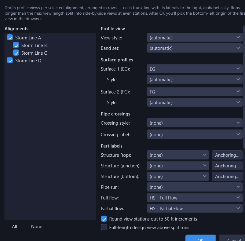
Spacing Settings
The dialog includes an Excel-style grid of spacing values:
| Setting | Description |
|---|---|
| Max view length | Longest station range a single view will cover, in feet (default 1000; enter 0 for no limit). Runs longer than this split into multiple views at even break stations measured from the alignment's beginning. |
| Grid before first view | Extra grid drafted before each run's first station, in feet: a 30 here starts the view at station -30 instead of 0. Only the first view of a run gets it (a split run's later pieces keep their even break stations), and it never counts against the max view length. |
| Row separation | Vertical clear distance between rows, in feet. Leave enough room to absorb band stacks hanging below the grid. |
| Gap between views | Horizontal clear distance between adjacent views, in feet. |
| Label clearance above/below | Grid height reserved below the lowest invert and above the highest ground or rim, in feet (default 5), providing room for the labels drafted along the top and bottom of the profile. At least this much is always kept: the datum and top then round outward to the 5-ft elevation grid, so rounding only ever adds clearance. |
| Minimum view height | Shortest grid a view will be given, in feet (default 30; enter 0 to size every view to its contents). A shallow run keeps its ground/rim-driven top and drops its datum to reach this height; a run whose pipes and surfaces need more room is unaffected. |
Gap and row separation are measured between what's actually drawn (grid, axis labels, bands), not between view boundaries, so the spacing you enter is the clear distance you'll see regardless of view style, including right-to-left graph styles.
Two additional checkboxes:
- Round view stations out to 50 ft increments (on by default): each view's station range is set explicitly to even 50-ft stations, rounding the start down and the end up, exactly as if you'd typed a user-specified range in Profile View Properties. A short lateral still gets a full grid to station 0+50 even if the alignment ends sooner.
- Full-length design view above split runs (off by default): when a run is split into pieces, also draft one full-length view of the entire run in its own row directly above the pieces, named
HS - {Alignment} (Design), so the whole run reads together while the pieces feed individual plan sheets.
How Long Runs Are Split
A run longer than the max view length is broken into several views at even stations, placed side by side, and named HS - {Alignment} (1 of N), (2 of N), and so on. The structure sitting on a break line is drawn in both neighboring views, like a match line between sheets.
Elevation Range and Surfaces
Each view's vertical grid is sized to cover that view's own pipes (inverts to crowns), structure rims, and sampled ground from the chosen surfaces, plus the label clearance above and below. A grid that comes out shorter than the minimum view height keeps its top and drops its datum to reach it. Split pieces size their grid to their own stretch of the run only, not the full alignment.
If the alignment already has a profile from the surface you picked for Surface 1 or Surface 2, HydraStorm reuses it as-is (its styling is left untouched); otherwise a new surface profile is created. Elevation bands on the view reference Surface 1 / Surface 2.
Crossing Pipes
Pipes from this network or any other network that cross a drafted run are drawn into the view using the crossing pipe style you selected, only within this view; the crossing pipe's own style elsewhere in the drawing is untouched.
The Crossing label combo lists the drawing's Crossing Pipe Profile label styles. That is a different Civil 3D category from the Plan Profile styles the pipe run and flow labels use, and it is the one a pipe crossing the alignment actually carries. Civil 3D has a separate label object for it. Leave the combo on (none) for no crossing labels.
HydraStorm authors no crossing label style; the annotation is your firm's, the same rule as the structure and pipe run labels. It does write its computed size, material and clearance (e.g. 24" RCP (1.35')) into a text component named HS_Crossing, so a style that defines a component by that name prints HydraStorm's clearance. A style that doesn't simply prints whatever Civil 3D properties it was built to print, and nothing is lost or reported.
Part Labels
The dialog's Part labels group has six style combos, each with a (none) option that skips that label:
| Combo | What it does |
|---|---|
| Structure (top) | Structure label style drafted above the grid |
| Structure (junction) | Drafted instead of the top style where three or more pipes meet |
| Structure (bottom) | Second structure label style, typically below the grid |
| Pipe run | The firm's own pipe label style, from the drawing |
| Full flow | Label for pipes running full, "HS - Full Flow": offered only when there are results |
| Partial flow | Label for pipes with a free surface, "HS - Partial Flow": offered only when there are results |
Junction Structures
A junction is a structure where three or more pipes meet: a lateral tying in, two mains meeting, or flow splitting off to a second line. Where the Structure (junction) combo names a style, those structures carry it instead of the top style; the bottom label is unchanged, so the sheet still reads one callout above the grid and one below.
Junctions are found from the network, not from the line being drawn, which means a tie-in carries the junction label in the trunk's view and in the lateral's own view, where the same structure is that run's downstream end. That is how a junction is annotated on a plan sheet: both lines say what happens there. A structure with two laterals still gets one label, and a null structure that is really a wye counts as a junction like any other.
Leave the combo on (none) and junctions read exactly as they did before; nothing changes until you pick a style.
Which Style Comes Up Selected
The structure and pipe run styles are the firm's own, taken from the drawing. HydraStorm authors none of them. To save you picking the same three every time, a project that hasn't chosen yet starts from the last selection you accepted in this dialog, on any project. With no previous selection to draw on, HydraStorm suggests a likely style from the drawing where it can and otherwise leaves the combo on (none). A first-time suggestion is worth a look before you click OK.
Once you accept the dialog, that selection is the project's, (none) included: a slot you deliberately switch off stays off the next time you open it.
A Saved Style or Surface This Drawing Doesn't Have
Every combo in this dialog (view style, band set, crossing style, both surfaces and their profile styles, crossing label, and the six Part label slots) is filled from what this drawing actually has. A name the project saved against a different drawing, or a per-user default carried in from another project, is not offered: as soon as the dialog opens, that slot falls back to (none) or, for the view, band set and surface profile styles, to the drawing's first style (shown by name), and a note above the option grid names exactly what was dropped, before you have picked anything or clicked OK. OK then saves what the combos show, so the dropped name does not come back on its own.
If Civil 3D reports no styles of a kind, or no surfaces at all, the saved name is kept rather than cleared.
Where the Structure Labels Sit
Each structure combo has an Anchoring… button beside it, setting where that label sits in the view. This is Civil 3D's own Dimension anchor option on the label (the same property the Properties palette shows when you select one), so the choices are Civil 3D's, spelled the same way:
| Anchor | What the single anchor value means |
|---|---|
| Graph View Top | How far down from the top of the grid. 0 sits flush with the grid top. |
| Graph View Bottom | How far up from the bottom of the grid. 0 sits flush with the grid bottom. |
| Distance Above / Distance Below | Measured from the structure itself, so the label rides up and down with it. |
| Fixed Elevation | An elevation in feet: the one option whose value is not a distance on the sheet. |
| (from label style) | No override: the label style's own default placement governs. Labels already in the drawing go back to it on the next draft. |
A label carries one number, the same Dimension anchor value the Properties palette shows. The usual pair is the top label anchored to Graph View Top and the bottom label to Graph View Bottom, both at 0, which is what a new project starts on. Except under Fixed Elevation, that number is a distance on the sheet at the view's plot scale rather than feet of elevation, so a 0.5 there is half an inch of paper.
The anchor is saved with the project and applies wherever HydraStorm places a structure label, including Output → Apply Label Styles. Change it and re-draft and the labels already in the drawing move with it; they aren't left on the old anchor. A label style that doesn't permit dimension anchors is left where its style puts it, and the run reports it.
Structure Labels
Every structure in the view gets both chosen labels, except null structures, which get none. A plain pipe-to-pipe splice has nothing a structure label could report. The exception to that exception: a null structure that's actually a fitting IS labeled: one whose part description or name carries a fitting keyword (wye, bend, tee, lateral, elbow, and similar, the same keyword list HydraStorm uses elsewhere), or one where the pipes change direction noticeably in plan.
Pipe Run Label
One label per run of pipe that doesn't change (same size, same slope, same material), placed on that run's middle segment at mid-span. Manholes and inlets do not break a run: a stretch of unchanging 24" RCP reads as one label no matter how many structures it passes through. When a long run is split into multiple views, a stretch cut by the split gets its own label in each piece.
The label reports the segment it sits on, not the whole run: a style with a length component prints that segment's length, not the total for the stretch it represents. The style itself comes from the drawing; HydraStorm doesn't author one.
Full / Partial Flow Labels
These two are the only labels a profile view carries that come from a calculation, so they're the only ones gated on one. With no successful calculation behind the drawing, both combos come up (none) and locked: the view drafts with its geometry and its Civil 3D property labels, and the flow labels wait. Your saved choice is kept and comes back as soon as a calculation succeeds. If results exist but are out of date, HydraStorm asks instead: recalculate and continue, draft without the flow labels, or cancel.
Full and partial flow labels are HydraStorm's own. A flow label covers a stretch of pipe whose label would read the same, so in practice each inflow starts a new flow label. They report the design storm: the Q line prints the return period as a subscript on the Q itself (e.g. "Q10 = 12.4 cfs"), naming which storm the number is.
A pipe counts as full when it's under pressure flow, surcharged, or carrying at or above its full-barrel capacity; otherwise it's partial. The starter styles show:
- Full flow ("HS - Full Flow"): Q, Qcap, V, Hv, Sf, n
- Partial flow ("HS - Partial Flow"): Q, Qcap, V, Dn, n
HydraStorm creates these on first use; after that they're yours to restyle in Civil 3D's label style editor, like any other label style. It never overwrites one that already exists.
Civil 3D pipes carry no capacity, velocity, or Manning's n property, so those numbers in a flow label come from HydraStorm's own calculation, not anything Civil 3D computes. Flow rate, HGL, EGL, junction loss, and return period ARE written to the pipe as standard Civil 3D properties, so a label style you author yourself can bind to those from Civil 3D's normal property list.
A flow label is only hung on a barrel that actually carries flow: a dry pipe (no design flow reaches it) gets no full/partial flow callout, the same rule every other HydraStorm report follows for a dry line. Re-applying (or re-drafting) after an edit that dries out a previously-flowing pipe, or flips it between full and partial, erases the stale label it no longer earns rather than leaving two callouts stacked.
Each flow label is drawn with a background mask at a fixed placement, so a long label stays readable over the grid.
Four of these six combos, namely Structure (top), Structure (junction), Full flow, and Partial flow, are the same setting as four of the five slots in Output → Apply Label Styles (which also has a Structure Style 2 slot, this dialog's Structure (bottom)); choosing a style in either dialog changes both. What differs is placement, not which style a part carries: Apply Label Styles puts a label on every part in every view, while Create Profile Views places one per run.
Re-Running
Views HydraStorm creates are named HS - {Alignment}… and are replaced in place the next time you run Create Profile Views; any views you built yourself are never touched. If you change the split settings (for example, the max view length) so that a previous split layout no longer applies, the outdated HydraStorm views from the prior run are removed automatically.
Drafted views are tracked: when calculation results change, the Output menu shows an out-of-date badge, and Output → Drafted Outputs lets you update them in place at their existing drawing locations without re-picking an origin. Flow label values count toward that tracking too: raising a drainage area upstream, with no geometry change at all, still badges the view out of date because what the full/partial flow labels would print has changed.
Tip
Run Create Profile Views before HGL Profiles and label styles: the views need to exist first so the HGL profile has somewhere to draft into.