Inlet Library
Inlet libraries define the types of inlets available for your project: their geometry, hydraulic calculation method, and capacity characteristics. HydraStorm ships with several built-in libraries and supports creating custom libraries for municipality-specific inlet types.
Built-In Libraries
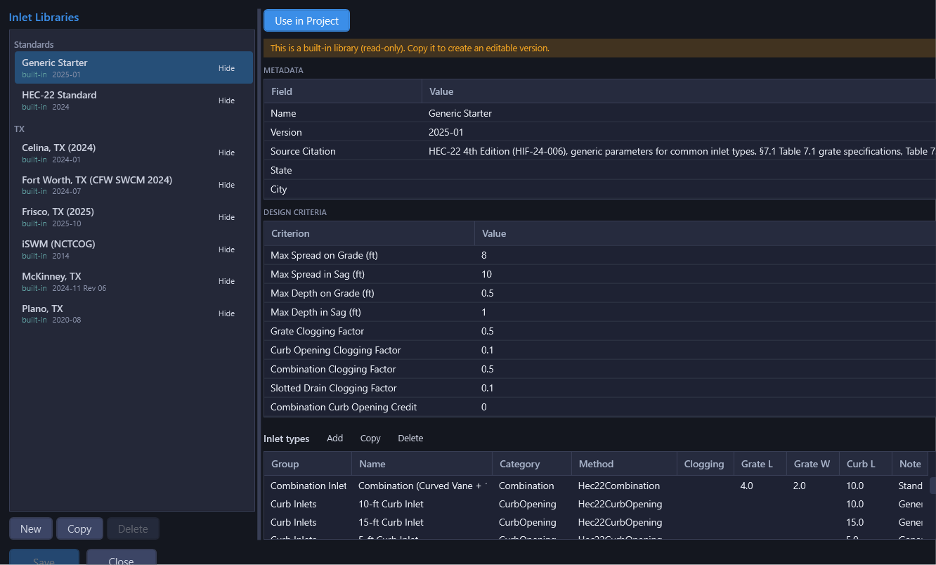
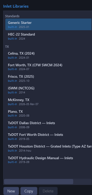
HydraStorm ships with twelve built-in inlet libraries:
| Library | Description |
|---|---|
| Generic Starter | Generic inlet types for getting started. Copy and customize for your needs. |
| HEC-22 Standard | Standard HEC-22 inlet types as defined in the FHWA manual. |
| iSWM (NCTCOG) | Inlet types per the NCTCOG iSWM (Integrated Stormwater Management) manual. |
| McKinney, TX | Municipality-specific inlets for McKinney, Texas. |
| Plano, TX | Municipality-specific inlets for Plano, Texas. |
| Fort Worth, TX (CFW SWCM 2024) | Municipality-specific inlets for the City of Fort Worth (Stormwater Criteria Manual, 2024). Distinct from the TxDOT Fort Worth District library below: same city, two different authorities with different standard details. |
| Frisco, TX (2025) | Municipality-specific inlets for Frisco, Texas. |
| Celina, TX (2024) | Municipality-specific inlets for Celina, Texas. |
| TxDOT Hydraulic Design Manual: Inlets | Statewide TxDOT inlet types per the Hydraulic Design Manual, Chapter 10. |
| TxDOT Dallas District: Inlets | District standard drawings (CI(1)-02(DAL), CI(2)-02(DAL), CI(2)-02-BC(DAL), STD 8 Type D drop inlet) governed by the TxDOT Hydraulic Design Manual, Chapter 10, Sections 4–6. |
| TxDOT Houston District: Grated Inlets (Type AZ family) | Grated inlets, Type AZ family, per Houston District standard drawings. |
| TxDOT Fort Worth District: Inlets | Fort Worth District standard drawings. Several grate types in this library publish clogging-reduced geometry. See Clogging Basis below before copying entries from it. |
Note: Built-in libraries are read-only. To customize one, use Copy to create an editable copy.
Inlet Type Categories
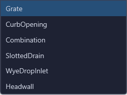
Each inlet type belongs to one of these categories, which determines the hydraulic method used to compute interception capacity:
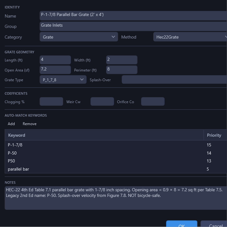
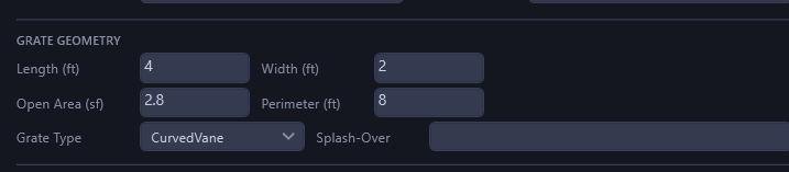
- Grate: Captures flow through openings in a grate surface. Geometry defined by grate length, width, open area, and perimeter. Uses HEC-22 4th Edition Chapter 7 grate interception equations.
- Curb Opening: Captures flow through an opening in the curb face. Geometry defined by opening length, height, and optional depression depth and width.
- Combination: A grate plus curb opening working together. Which of two published methods governs is the library/project's Combination Policy (see Library Design Criteria below). See Inlet Analysis for what each computes.
- Slotted Drain: A continuous slot along the gutter. Geometry defined by slot length and width.
- Wye/Drop Inlet: A box structure, always a sag. Its Opening style (Grated top or Side throats) decides whether it's rated as a grate in a sag or a curb opening on four sides. See Inlet Geometry Parameters below.
- Headwall: Pipe capacity method for headwall inlets. Capture equals the pipe full-flow capacity. No built-in library ships a Headwall type today; this category exists for legacy and user-authored entries.
Hydraulic Methods
Each inlet category uses a specific HEC-22 hydraulic method to compute interception capacity. The method is determined automatically by the category; you do not select it manually. HydraStorm's inlet equations are implemented against the FHWA HEC-22 4th Edition (2024, HIF-24-006), which consolidated pavement drainage (gutter flow, on-grade interception, and sag weir/orifice capacity) into a single chapter (Chapter 7); it superseded the 2nd/3rd Edition split where on-grade interception lived in Chapter 4.
| Category | Method | Reference |
|---|---|---|
| Grate | Hec22Grate | HEC-22 4th Ed §7.1 (on-grade) / §7.3 (sag) |
| Curb Opening | Hec22CurbOpening | HEC-22 4th Ed §7.2 (on-grade) / §7.3 (sag) |
| Combination | Hec22Combination | Grate + curb opening credit, HEC-22 4th Ed §7.3.4 |
| Slotted Drain | Hec22SlottedDrain | HEC-22 4th Ed slotted drain equations |
| Wye/Drop | PerimeterWeirOrifice | Weir/orifice calculation based on perimeter and area |
| Headwall | PipeCapacity | Capture = pipe full-flow capacity |
Note: On-grade inlets use the spread/velocity-based interception equations from HEC-22 4th Edition §7.1–7.2. Sag inlets use the weir/orifice equations from §7.3. Which one runs is decided by the Sag Inlet designation (see Inlet Analysis), not by slope directly: a Wye/Drop type or a None gutter section is always sag, by construction. An on-grade inlet whose gutter has zero or adverse longitudinal slope is a special case: the on-grade equations are undefined at flat slope, so HydraStorm falls back to the sag equations and warns on the row rather than dividing by zero.
Grate Types
For grate inlets, the grate type determines the splash-over velocity curve, the velocity at which water splashes over the grate instead of being captured. HEC-22 defines these standard grate types:
- P 1-7/8": Parallel bar, 1-7/8 inch on-center spacing, no transverse rods (not bicycle-safe; highest hydraulic efficiency)
- P 1-7/8-4: Parallel bar with 4 inch transverse rods (bicycle-safe)
- P 1-1/8": Parallel bar, 1-1/8 inch on-center spacing, no transverse rods
- Curved Vane: 3-1/4 inch longitudinal, 4-1/4 inch transverse spacing; direction-sensitive (vanes must face oncoming flow)
- 30° Tilt Bar: 3-1/4 inch longitudinal, 4 inch transverse spacing; direction-sensitive
- 45° Tilt Bar (2-1/4" spacing) and 45° Tilt Bar (3-1/4" spacing): two bar-spacing variants; HEC-22 does not publish an opening ratio for either and excludes both from sag service
- Reticuline: honeycomb grate; bicycle-safe but lowest debris handling and hydraulic efficiency of the set
Grate Selection Guidance
- Curved Vane grates have the highest capture efficiency for on-grade conditions and are the most commonly specified type in municipal standards.
- Reticuline grates have the lowest capture efficiency on-grade but are sometimes required for pedestrian safety in walkway areas.
- For sag conditions, the grate's open area and perimeter (not the grate type) determine capacity. All grate types with the same open area perform equally in sag.
Inlet Geometry Parameters
Each inlet type defines geometry parameters that feed into the hydraulic calculations. The required parameters depend on the inlet category:
| Parameter | Applies To | Description |
|---|---|---|
| Grate Length (ft) | Grate, Combination | Length of grate in direction of flow |
| Grate Width (ft) | Grate, Combination | Width of grate perpendicular to flow |
| Grate Open Area (sq ft) | Grate, Combination | Net open area of grate (used for sag weir/orifice calculations) |
| Grate Perimeter (ft) | Grate, Combination | Effective perimeter of grate (used for sag weir capacity) |
| Opening Length (ft) | Curb Opening, Combination | Length of curb opening along the curb face, the size the standard detail is drawn at |
| Published In (ft) | Curb Opening, Combination | Comma-separated list of every opening length the detail is published in (e.g. 5, 10, 15, 20). These become the choices in each inlet's Opening L picker; a one-off length can still be typed there. Blank means the detail comes in one size. Use one entry with a list rather than one entry per length: length is an input to the equations, so the sizes of a single detail are not separate inlet types. |
| Opening Height (ft) | Curb Opening, Combination | Height of curb opening |
| Depression Depth (ft) | Curb Opening, Combination, Slotted Drain | Local depression depth at the opening |
| Depression Width (ft) | Curb Opening, Combination, Slotted Drain | Width of depression |
| Slot Length (ft) | Slotted Drain | Total length of slotted drain |
| Slot Width (ft) | Slotted Drain | Width of slot opening |
| Opening Style | Wye/Drop | Grated Top (drop / area / yard inlet, a grate in the top) or Side Throats (Y-inlet, a top slab with a throat in each face, no grate). Decides which of the rows below apply and how the type is rated: a grate in a sag (weir on the rim perimeter, orifice through the grate's clear opening) versus a curb opening on four sides (weir on the throat-lip perimeter, orifice A = P·h to the throat centroid). |
| Opening L (ft) | Wye/Drop | Clear opening length in plan. Entering both length and width fills in the Perimeter below (P = 2(L + W)). |
| Opening W (ft) | Wye/Drop | Clear opening width in plan. |
| Perimeter (ft) | Wye/Drop | Weir perimeter, used by both styles. Derived from Opening L × W; editable to state a different convention. |
| Throat H (ft) | Wye/Drop, Side Throats only | Height of the throat opening in each of the four faces. The orifice area is P·h; required for a Y-inlet (a missing value carries the same "unbounded weir" warning a curb opening with no height gets). |
| Open Area (sq ft) | Wye/Drop, Grated Top only | The grate's clear opening, the sag orifice area. Blank seeds the full plan Opening L × W (the published municipal sump method, rated with the category's own clogging factor); enter the grate's own open area when its shop drawing states one. |
Like curb-opening details, HydraStorm ships one Wye/Drop entry per family, sized at the smallest published size, rather than one entry per size; the plan size at each structure is set per inlet (Opening L / Opening W, and the grate's Open Area override where it applies; see Inlet Dimensions in Inlet Analysis). Auto-matching keywords can carry both a length AND a width (e.g. a keyword of "4x4 drop" sets both dimensions at once), so a plan-size hint in the part description still sets full dimensions rather than just one.
Clogging Basis
Every inlet type carries a clogging basis that says whether its stored opening geometry is as-published, or already reduced for clogging at the source:
| Basis | Meaning |
|---|---|
| Raw (default) | Geometry is the full, unclogged opening as published. Clogging factors (per-inlet, per-type, or the library's per-category default) apply normally, in that priority order (see Clogging Factors). |
| PreReduced | The published grate area and perimeter are already clogging-reduced at the source: TxDOT's Fort Worth District standard drawings are the example this exists for. Because the geometry itself already accounts for blockage, HydraStorm applies no default clogging factor for these types: the category default from the library's design criteria is skipped entirely. An explicit per-inlet or per-type clogging factor still applies on top if you set one (it's declared intent, not a default), but doing so reduces an already-reduced opening a second time. HydraStorm flags this on the inlet's result as a warning naming the applied factor and calling out the double reduction, so it surfaces at calc time rather than staying a fact buried in a library note. |
Note: Clogging basis is set per inlet type when the library is authored and is not currently an editable field in the type grid. When copying a PreReduced type (e.g. from the TxDOT Fort Worth District library) into a custom library, leave its clogging factor blank and let the category default resolve to zero: the geometry is already doing the clogging reduction for you. Read the library's Notes before copying entries between libraries; that is where this kind of per-library convention is recorded.
A coefficient can be pre-reduced the same way an area can: an entry whose weir/orifice coefficients are the municipality's own reduced design values ships PreReduced too, and follows the same rule as the Fort Worth District grates above. Leave its clogging factor blank rather than stacking one on top.
Library Design Criteria
Each inlet library can optionally include design criteria that provide default limits for inlet analysis. When a library with criteria is applied to a project, these values are used unless overridden at the project level in Project Settings.
| Criterion | Description |
|---|---|
| Maximum spread on-grade (ft) | Allowable spread width for inlets on a continuous grade |
| Maximum spread at sag (ft) | Allowable spread width for inlets at sag (low) points |
| Maximum depth on-grade (ft) | Allowable ponding depth for on-grade inlets |
| Maximum depth at sag (ft) | Allowable ponding depth for sag inlets |
| Maximum spread on-grade, Check (ft) | Allowable on-grade spread when the inlet's own review storm is the check storm. Many manuals publish a looser check-storm allowance than the design allowance. |
| Maximum spread at sag, Check (ft) | Allowable sag spread for the check storm. |
| Maximum depth on-grade, Check (ft) | Allowable on-grade ponding depth for the check storm. |
| Maximum depth at sag, Check (ft) | Allowable sag ponding depth for the check storm. |
| Default clogging factors | Category-specific clogging percentages (e.g., 50% for grates, 10% for curb openings) |
| Combination Curb Opening Credit | Under the HEC-22 combination policy, the sweeper-credit fraction applied to the curb leg's contribution. Not read under the iSWM/Plano binary policy, which has no credit fraction. See the Combination Policy row below. |
| Combination Policy (HEC-22 / iSWM) | Which published method rates a combination inlet: HEC-22's sweeper-credit model or the iSWM/Plano grate-only-on-grade / curb-only-in-sag binary rule. See Inlet Analysis. |
| Depressed Curb Sag Weir Datum | Which depth a depressed curb opening's sag weir equation is evaluated at: a per-standard convention, ride library → project. |
| Rim Datum (gutter flowline / top of curb) | What a Civil 3D structure's rim elevation means for this library's inlets. See Rim Datum and Curb Height. |
| Curb Height (ft) | The curb height used to derive the gutter flowline under a Top of Curb rim datum (project default 0.5 ft when nothing is set anywhere in the chain). |
| Sag Weir/Orifice Transition | How a sag inlet's capacity composes across the weir/orifice handover band: the published (default) rule, or an alternate composition. See the Sag vs. On-Grade table in Inlet Analysis. |
Several municipal built-ins ship with no maximum spread at all. The iSWM (NCTCOG), Plano, McKinney, Fort Worth, TX (CFW SWCM 2024), Celina and Frisco libraries publish Maximum depth on-grade and Maximum depth at sag (0.5 ft, both the same value) but leave both Maximum spread rows blank: their source manuals state ponding as a depth-behind-curb limit and don't separately publish a spread number. Blank means no limit: applied as shipped, a project on one of these libraries will never flag a spread exceedance or show a spread failure on any inlet, on grade or in a sag, no matter how wide the water gets. Only the depth criterion is ever judged. If your street sections have a spread requirement (most do; check your governing manual and your own typical section), set Maximum spread on-grade and Maximum spread at sag as a project override in Project Settings rather than relying on the library default to catch it. The statewide TxDOT Hydraulic Design Manual library and its Dallas/Houston district companions do publish a spread limit (6.0 ft, from the interstate half-lane rule). Reset it too if your facility class differs.
Note: The four Check rows are optional. Leave any of them blank and that criterion's check-storm result is judged against the matching design-storm allowance instead. Blank is not "no limit," it means the library does not publish a separate, looser check-storm number. This only matters for a structure whose inlet review actually runs a check storm; see Inlet Storm Configuration.
Note: Library design criteria are defaults only. You can override any of these values in Project Settings for the current project without modifying the library itself.
Creating Custom Libraries
The Library Manager lays the right-hand editor out top to bottom as Metadata (name, state/city, source citation, version), then Library Notes, then Design Criteria, then the inlet type grid. The Notes field is where per-library conventions and rulings are recorded: things like a clogging basis on a specific grate family, a non-default depressed-curb weir datum, or a caveat about a source drawing's applicable range. It is read-only for built-in libraries (the same banner that locks the rest of the built-in editor locks it too) and becomes editable the moment you Copy a library. Read a library's Notes before copying entries out of it into another library. A convention that is correct in the source library's context (a clogging-reduced grate, a jurisdiction-specific coefficient) can silently misapply once the entry is sitting in a library that does not share that convention.
To create a custom inlet library for your municipality or project requirements:
- On the Inlet tab, click Library... in the property panel to open the Inlet Library Manager.
- Select a built-in library and click Copy to create an editable copy, or click New to start from scratch.
- Add inlet types with appropriate categories, geometry, and keywords.
- Configure geometry parameters to match the manufacturer specifications or municipal standard drawings for each inlet type.
- Optionally set library-level design criteria (spread limits, clogging factors) and record any conventions worth flagging in the Library Notes field.
- Save the library.
Custom libraries are saved to %LocalAppData%\HydraStorm\InletLibrary\. For firm-wide sharing across multiple workstations, set a custom library path in Program Settings.
Tips for Custom Libraries
- Start from the Generic Starter library if you need simple, generic inlet types. Start from a municipality-specific library if one matches your jurisdiction.
- Include keywords in each inlet type's description that match your Civil 3D part descriptions. This enables the smart matching system to suggest inlet types automatically.
- Set library-level design criteria to match your municipality's drainage design manual. This saves time on each new project by pre-populating the correct spread and depth limits.
- When creating inlet types for manufacturer-specific products, use the geometry values from the manufacturer's published specifications or shop drawings.
Smart Matching
Like junction loss types, inlet type assignments use a learning system. When you assign an inlet type to a structure, HydraStorm remembers the association between the Civil 3D part description and the inlet type. On future projects using the same inlet library, matching descriptions are suggested automatically.
The matching system:
- Follows your recent choices for a description, so changing your mind takes effect quickly
- Suggests more confidently the more consistently you assign a description
- Falls back to keyword matching when no learned history exists
- Is scoped per inlet library, so switching libraries resets suggestions
A keyword matches a complete code in the part description, not part of a longer one: a keyword CI-15 matches "CI-15 Curb Inlet" but not "CI-150 Curb Inlet".
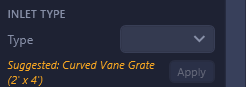
The suggestion shown for a structure states its own reason, so you don't have to guess why HydraStorm picked it: a keyword match shows the matched keyword (e.g. "Suggested: 10' Curb Inlet (matched 'CI-10')"), and a learned match states how many of your recent assignments for that description back it (e.g. "Suggested: 10' Curb Inlet (your last 3 assignments for this part)").
Note: Smart matching always suggests; it never auto-applies. The suggestion shows as a chip beneath the Type dropdown in the inlet property panel, naming its own reason, with an Apply button; you can accept it or pick a different type from the dropdown instead. This ensures you always have control over inlet assignments.