Culvert Analysis
HydraStorm includes a culvert analysis module based on FHWA HDS-5 (Hydraulic Design of Highway Culverts) methodology. Culvert alignments are analyzed separately from the storm drain network using inlet and outlet control headwater equations. This allows you to evaluate culvert crossings within the same Civil 3D pipe network model used for your storm drain design.
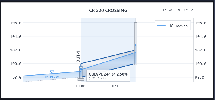
Alignment Design Types
Each alignment in your pipe network is classified as one of three design types:
| Design Type | Description |
|---|---|
| Storm Drain | Standard HGL/EGL propagation with junction losses, inlet capacity, and travel time accumulation. This is the default for all alignments. |
| Culvert | FHWA HDS-5 headwater analysis. Inlet control and outlet control headwater depths are computed independently, and the controlling condition (higher headwater) governs. Culvert alignments do not contribute to rational method travel time and do not participate in inlet analysis. Culvert pipes are entered and analyzed entirely on the Culvert tab: they don't appear in the storm drain results grid, and culvert alignments aren't offered in the storm drain profile's alignment dropdown. |
| None | Excluded from all calculations. Use this for alignments you want to ignore entirely. |
Set alignment design types in Tables > Alignment Types... on the main window toolbar.
Note: Changing an alignment from Storm Drain to Culvert removes it from the HGL/EGL network analysis. Any junction losses, inlet calculations, or travel time contributions associated with that alignment are excluded once the type is changed.
The Culvert Tab
Once at least one alignment is marked as a culvert, the Culvert tab holds everything for those crossings. Until then the tab prompts you to assign one. It has four regions:
- Profile view (top): the selected culvert alignment drawn to scale, with the barrel water surface, the headwater pool, the roadway embankment overlay, and the ground line. The ground line, and the roadway overlay where a roadway record exists, draw whether or not the crossing has been calculated. The View menu toggles HGL, EGL, and ground. Drag the splitter to trade profile height against grid height, or double-click it to collapse the grid.
- Stage-discharge chart: sits between the profile and the property panel. See Stage-Discharge Chart below.
- Property panel (right): the editable properties of the selected barrel, described below.
- Results grid (bottom): one row per pipe on a culvert-typed alignment, grouped by alignment, whether or not it has been calculated. See Results.
Note: A calculation that fails, or hasn't run yet, doesn't leave the tab empty. The profile still draws the crossing's geometry, the grid still lists every culvert pipe with its hydraulic columns blank (blank means not computed, never zero), and an in-place message explains why there are no numbers. A grid with no rows at all means the model has no pipe on a culvert-typed alignment.
Stage-Discharge Chart
The chart between the profile and the property panel is the selected barrel's headwater-vs-discharge performance curve: a reviewer's chart showing at a glance which control governs across the flow range and how much headroom the crossing has to the roadway crest. It draws from the barrel's geometry alone, so it's there before you've assigned a storm or run a calculation. It shows:
- the governing headwater curve (solid blue): the composite curve including relief from roadway overtopping above the crest, once a roadway record exists
- the inlet control curve (dashed orange)
- the outlet control curve (dotted green)
- reference lines at the barrel crown and the roadway crest
- markers for the computed design and check operating points, once results exist
For a chained run of culvert pipes, the chart describes the selected barrel alone; the published results in the grid still come from the full run analysis.
Property Panel
Select a culvert pipe in the results grid or the profile view, then edit it here. Prev and Next (or the left and right arrow keys) step along the run. Every edit recalculates live; pressing Enter in a numeric field commits it immediately, the same as a grid cell. Apply pushes the changes to Civil 3D and Discard reverts them.
| Field | Description |
|---|---|
| Shape | Circular or box. Changing it re-filters the entrance type list and the size editors to match. |
| Family | Civil 3D part family for the barrel. Sets the material and determines which sizes the grid's Size and Span cells offer. It does not change Manning's n. |
| Mannings n | Barrel roughness coefficient, read from the drawing and editable per barrel. The barrel is sized and checked on this value. |
| Entrance | FHWA entrance configuration, filtered to the barrel shape. See Entrance Types. |
| Barrels | Number of identical parallel barrels. See Multi-Barrel Culverts. |
| Roadway... | Opens the roadway record for this crossing. See Roadway Overtopping. |
| Condition (Tailwater) | Free Outfall, Specified Elevation, Downstream Channel, or Crown, with the channel parameters appearing when that option is chosen. See Tailwater Conditions. |
| InvUS / InvDS | Inlet and outlet invert elevations. These are flow-oriented from the network topology, not the direction the barrel happens to have been drawn in Civil 3D. Headwater elevation is referenced to InvUS, tailwater depth to InvDS. Slope is derived from the two, so there is no separate slope field. |
Editing Barrel Size
The Size and Span cells in the results grid are editable, the same way they are in the storm drain grid:
- Circular barrels: the Size cell picks a diameter from the part family's catalog. The Span cell is blank.
- Box barrels: the Span cell picks the inside width from the catalog's available spans, and the Size cell then picks the rise from the rises available at that span. Changing the span snaps the rise to the nearest available value.
Where the drawing has no box part family loaded, both cells accept a typed dimension instead.
Entering Design Flow
The crossing's design flow is entered directly on the culvert results grid, on the same row that reports headwater and velocity. Which columns appear follows the same rule as the Hydrology table:
- Peak Flow Only mode, or HydraLink linked under the Peak Flows import basis: an editable Q column accepts the crossing's flow in cfs.
- Manual mode, or HydraLink linked under the Basin Parameters import basis: C, A, and Tc columns replace it, and the grid computes Q from them off the project's IDF data. They are editable in Manual mode; under a HydraLink link they are filled read-only from the linked file, the same as everywhere else those columns appear.
What you enter here is priced at the culvert module's own design return period, which can differ from the storm drain's; see Culvert Storm Events below. When the culvert module also runs an independent check storm, that check-period flow is entered separately, in the per-storm flow columns of the Hydrology table. The grid's total-flow result column is labeled Qtot.
How Culvert Analysis Works
For each pipe in a culvert alignment, HydraStorm works through three steps to determine the controlling headwater, then resolves the water surface through the barrel:
1. Inlet Control
Headwater depth is computed from the entrance type and culvert geometry. This represents the headwater depth required to push flow into the barrel. In inlet control, the barrel has more than enough capacity to convey the flow: the entrance is the bottleneck.
The inlet control coefficients are the FHWA published set, so inlet control headwater agrees with an equivalent HY-8 run rather than approximating it.
2. Outlet Control
Headwater depth is computed from the entrance loss, friction loss through the barrel, velocity head, and the tailwater at the outlet. This represents the headwater depth required to push flow through and out of the barrel. In outlet control, the barrel length, roughness, and downstream conditions limit the capacity.
That equation describes a barrel flowing full. A culvert that is only partially full is solved against its actual water surface instead, so outlet control headwater on a partly full barrel is not a full-barrel approximation.
Ke, the entrance loss coefficient, comes from the entrance type. A design standard's criteria can override Ke for a given entrance type, in which case the override is what the calculation uses.
3. Controlling Condition
The higher of the two headwater depths governs the design:
- Inlet controlled: HWic > HWoc. The barrel capacity exceeds the entrance capacity. Increasing the barrel size will not reduce headwater; improving the entrance geometry (e.g., adding beveled edges or a wingwall) is the effective solution.
- Outlet controlled: HWoc > HWic. Barrel friction and tailwater conditions limit the capacity. Increasing the barrel size, reducing the barrel length, or lowering tailwater will reduce headwater.
The headwater elevation must remain below allowable levels, typically the roadway overtopping elevation or other project-specific criteria.
4. Barrel Water Surface
Along with the headwater, HydraStorm resolves the water surface through the barrel and draws it in the profile view. The reported outlet depth and outlet velocity are read from the downstream end of that same surface, so the drawing, the grid, and the velocity you would size riprap against always agree with each other.
The grid's Regime cell states what the barrel is doing: the governing control and how full the barrel runs, as one phrase ("Inlet · Unsubmerged", "Outlet · Full Flow"). Hover it for the two further classifications the exports carry as their own columns:
- Slope Type: Steep or Mild.
- Barrel Condition: Full Flow, Full at Inlet / Partial at Outlet, Partially Full, Partially Full (Supercritical), Partially Full with Hydraulic Jump, or Jump at Outlet Face.
Where a hydraulic jump stands inside the barrel, the profile draws the front and labels it HYD JUMP. A jump that resolves at the outlet face or downstream of the barrel is reported in the Barrel Condition classification but is not drawn inside the barrel. The culvert jump is located as HY-8 locates it, with sequent depths that are not adjusted for the barrel's slope. A storm drain pipe's jump does count the slope, so the same steep barrel can show its jump further toward the outlet when it is analyzed as a storm drain.
Note: On a mild slope discharging to low tailwater, the outlet depth reported is the brink depth at the outlet, not normal depth. Normal depth would overstate the depth and understate the outlet velocity, which is the non-conservative direction for sizing riprap or an energy dissipator.
Entrance Types
The entrance type selects the inlet control coefficient set and the outlet control entrance loss coefficient Ke. Select the entrance type that best matches the field condition for each culvert pipe.
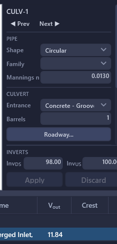
The Entrance dropdown is filtered to the barrel's shape: a circular barrel offers only the nine circular entrances, a box barrel only the six box entrances. The two sets are not interchangeable, because the HY-8 inlet control coefficients are fitted per shape. If a project file carries an entrance type that no longer matches its barrel (after a circular-to-box swap in Civil 3D, for instance), the culvert results row raises a warning saying the headwater is unreliable until a matching entrance is selected.
Circular Culverts
Concrete and corrugated metal entrances appear in one list, prefixed by material.
| Entrance Type | Description |
|---|---|
| Concrete - Square Edge w/ Headwall | Conventional concrete headwall with a square-edged opening |
| Concrete - Groove End w/ Headwall | Pipe with a groove (bell) end set in a headwall |
| Concrete - Groove End Projecting | Pipe with a groove end projecting from the fill |
| Concrete - Beveled Edge (1:1) | 45-degree bevel around the entrance |
| Concrete - Beveled Edge (1.5:1) | 33.7-degree bevel, the more efficient of the two standard bevels |
| Concrete - Mitered to Slope | Concrete pipe cut to conform to the embankment slope |
| CMP - Headwall | Corrugated metal pipe set in a headwall |
| CMP - Thin Wall Projecting | Thin-wall metal pipe projecting from the fill |
| CMP - Mitered to Slope | Metal pipe cut to conform to the embankment slope |
Box (Rectangular) Culverts
| Entrance Type | Description |
|---|---|
| Box - Square Edge | Conventional headwall with square edges on all sides |
| Box - Beveled Edge (1.5:1) | 33.7-degree bevel on the top edge |
| Box - Beveled Edge (1:1) | 45-degree bevel on the top edge |
| Box - Wingwall 30-75 | Wingwalls flared 30 to 75 degrees from the barrel axis |
| Box - Wingwall 90/15 | Wingwalls at 90 degrees (a flush headwall, square to the barrel) or flared only 15 degrees |
| Box - Wingwall 0 (Side Ext.) | No flare: the wingwalls run parallel to the barrel as extensions of its sides |
Note: Box culverts have no groove end. Precast box sections are cast with a tongue-and-groove joint, but that joint is not a hydraulic entrance condition. Where a box entrance appears in the field to have a rounded or chamfered lip, the corresponding FHWA curve is one of the two bevels.
Choosing an Entrance Type
- The entrance type significantly affects inlet control headwater. A beveled or groove-end entrance can reduce headwater by 0.5D or more compared to a square-edged entrance.
- When in doubt, use the most conservative (least efficient) entrance type that matches the proposed construction. You can always refine later once entrance details are finalized.
- Refer to FHWA HDS-5 Chapter 3 for photographs and detailed descriptions of each entrance condition.
Multi-Barrel Culverts
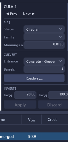
Set the number of barrels per culvert pipe to model side-by-side barrel configurations. The total capacity equals the single-barrel capacity multiplied by the barrel count. Each barrel is assumed to be identical in size and slope.
Adjust the barrel count in the culvert properties panel for the selected pipe. Common configurations include twin (2) and triple (3) barrel crossings.
Note: Multi-barrel culverts divide the total design flow equally among all barrels. The headwater computation uses the per-barrel flow (Q / N) for each barrel, then reports the resulting headwater for the combined system.
Tailwater Conditions
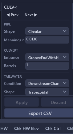
The tailwater elevation at the culvert outlet directly affects outlet control headwater. It is set in one place: the Tailwater section of the culvert properties panel. HydraStorm provides four tailwater options:
| Tailwater Option | Description | When to Use |
|---|---|---|
| Free Outfall | No tailwater influence. The outlet discharges freely with tailwater = 0. | Culvert discharges to an open channel with no downstream backwater effect (e.g., a steep channel or drop structure). |
| Specified Elevation | Enter the tailwater elevation for each storm: the box is labeled with the storm the toolbar selector shows, and blank means that storm states none (it is solved as a free outfall). | Tailwater is known from a separate hydraulic analysis, floodplain study, or design constraint (e.g., detention pond water surface). |
| Downstream Channel | HydraStorm computes the tailwater normal depth in a downstream channel using Manning's equation. | Culvert discharges to a channel where normal depth is a reasonable approximation of tailwater. |
| Crown | The tailwater stands at the top of the barrel: the outlet invert plus the rise (the diameter of a pipe, the height of a box). The outlet is submerged exactly, and outlet control is solved full-barrel with ho = D. Because it is barrel geometry rather than a stage, there is nothing to enter per storm and it follows the barrel if you resize or move it. | The stage below the crossing isn't known and you want a conservative starting point, or the outlet is known to run submerged. Matches the Crown tailwater method on the storm drain side. |
Parallel barrels share one tailwater. Barrels drawn side by side at one crossing discharge into one pool, so setting the condition, the elevation or the channel on any of them sets all of them: the panel names the barrels it will change, and one undo reverts them together. A barrel partway down a culvert that runs through a junction box takes its tailwater from the barrel below it; its tailwater controls are greyed out and the panel names that barrel.
The road uses the same tailwater. When a roadway overtops, the weir's submergence factor kt is read from the culvert's tailwater, one downstream stage for barrel and road, as HY-8 does.
Downstream Channel Parameters
When the Downstream Channel option is selected, specify the following channel properties:
- Channel Shape: Rectangular, Trapezoidal, or V-Shape
- Manning's n: Channel roughness coefficient
- Slope: Channel longitudinal slope (ft/ft)
- Bottom Width: Channel bottom width (ft); not applicable for V-Shape
- Side Slopes: Horizontal to vertical ratio (H:1V); applicable to Trapezoidal and V-Shape
Normal depth is computed iteratively from Manning's equation and used as the tailwater elevation at the culvert outlet invert. A channel that can't carry any flow at all (a missing or non-positive slope, or a rectangular/trapezoidal section with no width and, for trapezoidal, no side slope either) falls back to free outfall and raises a warning naming which parameter is missing or invalid, rather than silently reporting zero tailwater.
Roadway Overtopping
When the headwater pool at a culvert crossing rises to the roadway crest, the road itself starts carrying flow. HydraStorm models this per FHWA HDS-5 §3.1.5: once the pool reaches the crest, it solves for a single balanced headwater elevation at which the barrel (still governed by its own inlet/outlet control headwater) and the road, acting as a broad-crested weir, together pass the full design flow.
Setting Up a Roadway Record
Roadway records live in Tables > Culvert Roadways..., one row per culvert alignment: a single embankment shared across every barrel and pipe segment in that crossing.
| Field | Description |
|---|---|
| On | Master switch. Uncheck to keep the record (crest, lengths, surface) without running overtopping analysis on that crossing. |
| Crest Elev | Roadway crest elevation (ft): the weir crest. Leave blank until seeded or entered; overtopping analysis is skipped, with a warning, until it's set. |
| L (ft) | Weir crest length, measured along the road, perpendicular to the barrel: the L in Qo = kt·Cr·L·HWr1.5. User input, never derived. |
| Lr (ft) | Crest width in the direction of flow over the weir (pavement + shoulders), parallel to the barrel. Selects the HDS-5 Figure 3.11 discharge-coefficient chart: HWr/Lr > 0.15 uses the deep-overtopping chart. |
| Surface | Paved or Gravel. Selects which Cr/kt curve family from Figure 3.11 applies: gravel discharges less efficiently at the same head. |
| Crest (shape) | Level (flat grade, the full pool depth runs the weir equation directly) or Sag Vertical Curve (the road dips over the crossing; HydraStorm uses the HDS-5 hydraulic-depth representation instead of full ponded depth, which would otherwise overstate the relief). |
| US Slope / DS Slope / Sta | Embankment face slopes (H:V) and the crossing's profile station. They place the modeled embankment overlay in the profile view and have no effect on the flow split, but together with Crest Elev and Lr they do feed a plausibility check: if the crest width plus the two face slopes run out past the ends of the barrel, the modeled embankment doesn't fit on the culvert it's assigned to, and the crossing raises a warning naming the shortfall. Clear it by lengthening the culvert, steepening the face slopes, or double-checking the crest elevation and Lr entries: whichever of those was actually wrong for this crossing. |
Note: A blank Crest Elev means "no crest recorded yet," not "the road never overtops." A crossing without a crest elevation is skipped entirely: enter or seed one to get an overtopping analysis at all.
Seeding the Crest from the Surface
The Seed button on each row proposes a crest from the active Civil 3D surface instead of requiring you to look it up manually. Where the road sags across the crossing, it also proposes Sag Vertical Curve. Where the surface suggests the crossing may be skewed, it warns you: HydraStorm models crossings as perpendicular to the barrel only, so verify the crest by hand if you see that warning. Review the seeded values before accepting them; nothing is written to the row until you do (suggest-and-confirm, the same pattern as loss and inlet type matching).
How the Flow Split Works
Below the crest, a culvert behaves exactly as described above: inlet or outlet control governs, full stop. Once the rising pool reaches the crest, the road starts discharging as a broad-crested weir:
where HWr is the headwater above the crest, Cr is the discharge coefficient (HDS-5 Figure 3.11, by surface and HWr/Lr), and kt is a submergence factor that reduces the road's capacity as the downstream water surface rises toward the crest. HydraStorm solves for the single headwater elevation at which the barrel's own flow, from its controlling headwater equation, plus Qo equal the total design flow: the barrel doesn't get to keep passing its full-headwater capacity once the road starts relieving it.
What You'll See When a Storm Overtops
- The culvert results grid's Crest, Qover, and Freeboard columns fill in, for whichever storm the toolbar selector shows; see Results below.
- The profile view draws the modeled embankment (dash-dot line) over the sampled ground, plus the overtopping pond and a schematic sheet flowing down the far face when a storm actually overtops, labeled "OVERTOPPING X cfs".
- When a culvert crossing sits below a storm drain run, the balanced headwater elevation (overtopping included) is what seeds the storm drain's HGL at the pipe entering the crossing, the same way an un-overtopped culvert's headwater already does.
Headwall Entrance Losses on Storm Drain Pipes
Some storm drain runs begin at an open channel, ditch, or basin rather than another pipe: a headwall structure with no pipe flowing into it. A generic junction loss coefficient doesn't represent the physics at this kind of structure, so HydraStorm can apply the same FHWA HDS-5 inlet/outlet control analysis used for culvert alignments to the storm drain pipe's own upstream-most node.
Assign an entrance type in the Headwall (HDS-5) column of the Minor Losses Table. The dropdown is only enabled for a node with no incoming pipes (the top of a run), and the list of entrance types is filtered to match that pipe's shape (circular or box). Leave the column at — None — to keep the ordinary junction-loss calculation at that node.
When a headwall entrance type is assigned, HydraStorm computes the culvert headwater for the downstream pipe (using that pipe's downstream HGL as tailwater) instead of a junction loss, and reports the resulting headwater elevation as the structure's HGL. This is independent of the alignment's design type: it applies to a dead-end structure on a Storm Drain-type alignment, not to a separate Culvert alignment.
Note: The headwall entrance type is only selectable for structures with zero incoming pipes. It has no effect once a structure has an upstream pipe connected; that structure always uses the ordinary junction-loss calculation.
Culvert Storm Events
Culvert alignments can use independent storm return periods from the storm drain network. This is common in practice: for example, you might design storm drains for a 25-year event but analyze culverts at a 50-year or 100-year event, reflecting the higher consequence of culvert overtopping.
Assign them in Project Settings > Culverts > Storm Events. The list is built from the return periods the project analyzes, which are defined on the Hydrology tab; add one here and give it the Design or Check role for the culvert module. Both roles are supported, so culvert performance can be evaluated at two independent return periods.
Note: There is no separate on/off switch. Leave the Storm Events list empty and culvert alignments run on the storm drain's own design and check storms. Adding a storm here is what makes the culvert storms independent.
An independent culvert storm needs flows of its own. In the rational modes, HydraStorm re-walks the network at the culvert's return period and reads that period's intensity off the IDF curve: enter the C/A/Tc for the crossing on the culvert grid itself, as described in Entering Design Flow above, and nothing else is required beyond an IDF row for the period. In Peak Flow Only mode, and for flows imported from HydraLink, enter the design-period Q directly on the same culvert grid row; if the culvert module's check period also differs from the storm drain's, enter that flow in the per-storm flow columns of the Hydrology table instead. Only the culvert barrels move to the culvert storm; the storm drain system upstream keeps its own.
If nobody entered flows for the culvert's storm, the crossing accumulates zero, and a culvert carrying no flow returns a headwater at the invert, which passes every criterion you set. HydraStorm will not let that stand silently: each barrel that computes dry at the culvert storm while carrying flow at the storm drain storm raises a warning naming both, so you can enter the missing storm or point the culvert module at one the project already models.
Which Storm Seeds the Storm Drain's HGL
Where a culvert crossing sits below a storm drain run, the crossing's headwater seeds the storm drain's HGL at the pipe entering it, but always at the storm drain's own storm, never the culvert module's independent one. The seed is the water surface standing in the crossing's headwater pool, so the correct boundary for the storm drain's 10-year HGL is that pool at the 10-year storm; a 100-year crossing headwater would stand a water surface against pipe flows that never actually coexist with it. An informational calculation message names which storm seeded the boundary whenever the two periods differ, so the convention is stated rather than left for you to infer from a table heading. If you deliberately want to check the storm drain against a higher receiving-water surface, set that storm's tailwater or downstream HGL directly on the outfall: that's a tailwater decision, not a side effect of the culvert period.
Enabling only the culvert module's Check storm (with no storm drain check storm of your own) doesn't publish a storm-drain check storm as a side effect. The crossing headwater that seeds each storm drain storm's HGL (described above) is not published as a culvert result: no check columns appear in the storm-drain grid, no "Storm Calcs (Check)" sheet is added to the export, and no check CAD tables or HGL profiles are drafted for a storm drain check storm you never enabled. Only the culvert results grid itself publishes at the culvert module's Design and Check periods, titled with those periods in the grid, the culvert CAD schedule, and the workbook's culvert sheet: a project routinely sets the culvert module's own periods away from the storm drain's, and the crossings are always labeled with the storm they were actually analyzed at.
The rest of the culvert hydraulic parameters, including Manning's n defaults, the tailwater method, and cover, come from the Storm Drain tab of Project Settings. Only the storm events and the compliance limits below are culvert-specific.
Results
Culvert results fill the grid at the bottom of the Culvert tab, one row per culvert pipe and grouped by alignment. The grid reports the controlling headwater condition for each barrel along with the key hydraulic parameters. A row shaded amber carries a warning; hover it to read the warning text.
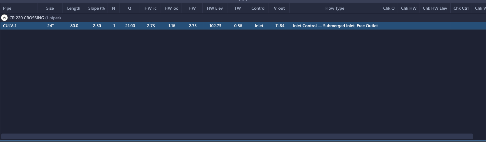
Design Storm Columns
| Column | Description |
|---|---|
| Pipe | Barrel name from the Civil 3D pipe network |
| Length | Barrel length (ft) |
| N | Number of barrels |
| Span | Inside width for a box barrel (ft); blank for circular. Editable |
| Size | Diameter for a circular barrel, rise for a box barrel. Editable |
| Slope % | Barrel slope as a percentage |
| InvUS | Inlet invert elevation (ft), flow-oriented. This is the datum for headwater elevation. Edit it in the property panel |
| InvDS | Outlet invert elevation (ft), flow-oriented. Edit it in the property panel |
| Entrance | The FHWA HDS-5 entrance configuration, which selects the inlet-control curve. Edit it in the property panel or the Minor Losses table |
| Qtot (cfs) | Total flow to the crossing at the selected storm. The entry columns to its left (Q in Peak Flow Only mode and for HydraLink flows imported under the Peak Flows basis; C, A, Tc in Manual mode and Basin Parameters HydraLink) are where the crossing's design flow is entered; see Entering Design Flow above |
| TW (ft) | Tailwater depth at the outlet: an input to the outlet-control headwater, so it sits ahead of the headwater columns the way it does on the HDS-5 form |
| HWic (ft) | Inlet control headwater depth above the inlet invert |
| HWoc (ft) | Outlet control headwater depth above the inlet invert |
| HW (ft) | Controlling headwater depth: the maximum of HWic and HWoc |
| HW Elev (ft) | Headwater elevation (inlet invert elevation + HW depth) |
| Regime | Governing control and flow regime as one phrase: "Inlet · Unsubmerged", "Outlet · Full Flow". Hover for the barrel condition and slope type |
| Vout (ft/s) | Outlet velocity, computed at the resolved outlet depth. Important for erosion protection design at the culvert discharge point |
| Crest (ft) | Roadway crest elevation, from the roadway record. Blank when the crossing has no roadway record. |
| Qover (cfs) | Flow over the road. The culvert barrel carries Q − Qover. Zero when the pool hasn't reached the crest. |
| Freeboard (ft) | Crest elevation minus headwater elevation. Negative means the road is overtopped by that depth. |
| Criteria | Verdict against the culvert compliance limits: blank when no limits are set, OK when every applicable limit passes, or ✗ n counting the violations across both the design and check storms. Hover for the list, each violation named with its storm; this is the one cell on the grid that speaks for a storm other than the selected one. |
One Storm at a Time
Each row describes the crossing at one storm: the one the toolbar's Storm selector shows. On the Culvert tab that selector lists the culvert module's storms: its own design and check periods when the module has a storm list of its own (a 100-yr crossing under a 10-yr storm drain), or the storm drain's storms when it follows them. Switch the selector to read the check storm; there are no side-by-side check columns, because a second set of headings duplicated a selector position and, with the check storm selected, held the design storm's numbers under a "check" heading. The drafted culvert schedule and the workbook's culvert sheet report the same storms the selector lists, one row per storm, so the screen and the outputs can never name different storms.
Interpreting Culvert Results
- Compare the HW Elev to your allowable headwater elevation (roadway overtopping elevation). If HW Elev exceeds the allowable level, increase the culvert size, add barrels, or improve the entrance type.
- High outlet velocities may require energy dissipation or erosion protection at the downstream end. Check local jurisdiction requirements for maximum allowable outlet velocity.
- A culvert that is inlet controlled under the design storm may become outlet controlled under the check storm as tailwater rises. Always verify both conditions.
- Once Qover is nonzero, the road is doing real work relieving the barrel, so don't read HW Elev alone as "the culvert failed." Check Freeboard and the share of the flow going over (Qover against Qtot) to judge whether the overtopping itself is acceptable for the storm in question.
Design Criteria (Compliance Limits)
Culvert-specific compliance limits live in Project Settings > Culverts > Design Criteria, separate from the storm drain's own Design Constraints. Four limits, each blank by default (not enforced):
| Limit | Storm | Description |
|---|---|---|
| Max HW/D | Design | Maximum headwater-to-rise ratio. D is the barrel rise for both circular and box culverts. |
| Min Freeboard to Road, Design | Design | Minimum clearance from the design-storm headwater to the roadway crest. |
| Min Freeboard to Road, Check | Check | Minimum clearance at the check storm. Enter 0 to mean "the road must not overtop at the check storm": any overtopping fails the check, it isn't tolerated at zero freeboard. |
| Max Outlet Velocity | Design | Maximum barrel outlet velocity, for erosion/energy-dissipation screening. |
Freeboard limits can only be judged on a crossing with a usable roadway record. A crossing with a freeboard limit set but no roadway record, or one with an unresolved crest, is never failed for it; instead an advisory message reports that freeboard was not evaluated at that crossing.
A design standard's design criteria can prescribe these four values along with the rest of its recommended settings; they arrive through the usual design-criteria adoption prompt when you apply the standard.
Where Verdicts Appear
- The results grid's Criteria column: blank when no limits are set, OK when every applicable limit passes, or ✗ n (n = violation count across the design and check storms combined) with the specific violations on hover, each named with its storm.
- Calculation messages list each violation individually.
- The Excel export's culvert sheet and the drafted culvert schedule carry a Criteria column per storm row: each row states its own storm's verdict, so no merge is needed there.
Getting Culvert Results Out
Two routes, both reporting the same computed numbers: the workbook's culvert sheet is the output now that the panel's CSV export has been removed:
- Output > Export > Excel Workbook...: the workbook includes a Culvert Calcs sheet alongside the storm drain sheets.
- Output > Tables to Drawing > Culvert Table...: drafts one combined culvert schedule as a native AutoCAD table covering every culvert-designated alignment. Re-running replaces the tracked table in place rather than stacking a second one. When the drafted table no longer matches the current results, the menu item turns amber to flag it as out of date.
Both share one column list and one row order, so the drawing and the submitted workbook agree cell for cell. Storms are rows: each crossing is a block of one row per reported storm (design, check, and any analysis storm the module follows) with a Storm column naming it ("10-yr Design", "100-yr Check") and the crossing's own facts (size, shape, entrance, length, slope, n) stated on the block's first row. A third storm is one more row, not another set of headings, and the design-versus-check comparison a reviewer makes on freeboard or headwater sits vertically adjacent. The title names every storm drafted.