Property Panel
On the Storm Drain and Culvert tabs, the property panel is docked inline to the right of the profile canvas (not a separate window) and shows a compact set of fields for the currently selected pipe: navigation, slope settings, shape/part family, junction loss assignment, and invert elevations. Pipe size, friction coefficient, and design flow are edited directly in the results grid instead of here. All edits take effect immediately in the profile view and trigger an automatic recalculation. Multi-pipe editing actions like Raise/Lower, Set Slope, Match Slope, and Match to Adjacent are available via the right-click context menu on the profile or grid (see Pipe Editing), not from panel controls.
Note: The Inlet tab has its own separate right-side panel for inlet type, gutter section, and bypass settings; see Inlet Analysis.
Pipe Navigation
At the top of the property panel, ◀ Prev and Next ▶ buttons let you step through pipes in the network sequentially. You can also use the Left and Right arrow keys as a keyboard shortcut. The current pipe name is displayed above the navigation buttons.
Slope
| Field | Description |
|---|---|
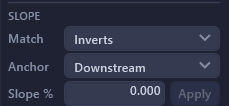
| Match | Dropdown to select the structure transition criterion used when applying a continuous slope across multiple pipes: Inverts (fixed structure drop), Centerlines, or Crowns. |
| Anchor | Dropdown to select which end is held fixed during slope operations: Downstream (hold outfall end, adjust upstream) or Upstream (hold headwater end, adjust downstream). |
There is no Slope % quick-apply field in the panel. Match and Anchor only set the criteria that Set Slope... (right-click the profile or grid, or Ctrl+Shift+L) uses when it lays out multiple selected pipes.
Editing Tools in the Context Menu
Pipe editing actions such as Raise/Lower (Ctrl+Shift+R), Set Slope... (Ctrl+Shift+L), Match Slope (Ctrl+M), and Match to Adjacent (invert, crown, or centerline) are accessed by right-clicking a pipe in the profile view or results grid; none of these live as buttons in the property panel. See Pipe Editing for details on each command and keyboard shortcuts.
Inverts
Below Junction Loss, an INVERTS section holds editable InvDS and InvUS fields for the selected pipe, the hydraulic downstream and upstream ends per the network topology, regardless of which direction the pipe was drawn in Civil 3D. Changing an invert recomputes slope holding the other invert fixed. With multiple pipes selected, editing one end sets that end of the whole run and re-lays the chain at constant slope. (Size and Manning's n stay in the results grid.)
Run Navigation
At a junction where a lateral ties into a trunk, two buttons appear below Inverts: ◀ To Main jumps the panel and profile selection to the trunk pipe receiving this lateral, and To Lateral ▶ jumps to a lateral tying in at the selected pipe's upstream structure. When more than one lateral ties in at that structure, right-click To Lateral ▶ for a menu listing each one by name so you can pick which to jump to. Either button is disabled, with a tooltip explaining why, when there's nothing to navigate to in that direction.
Pipe
| Field | Description |
|---|---|
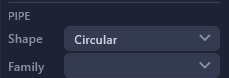
| Shape | Pipe cross-section shape: Circular or Box. Switching to Box enables the Span column in the results grid; on Apply the pipe swaps to a matching part family in Civil 3D. |
| Family | Dropdown to choose the pipe material and type from the Civil 3D parts list (e.g., "Concrete - Circular Pipe", "RCP Class III"). Changing the part family may change the available sizes. It does not change Manning's n. Auto Design sizes each pipe from its own family, so set the family here before you run it. |
Size, span (box pipes), and friction coefficient (Manning's n or Hazen-Williams C) are edited in the results grid's Size, Span, and Mannings n columns.
Junction Loss
| Field | Description |
|---|---|
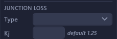
| Type | Dropdown to assign a junction loss type from the active design standard to the selected pipe's upstream node. The list shows all loss types defined in the selected standard. HydraStorm suggests loss types by matching Civil 3D part descriptions (see Junction Losses); suggestions are confirmed in the Minor Losses table, never auto-applied. This dropdown lets you override the assignment for the currently selected pipe directly. |
| Kj | Manual override for the junction loss coefficient, shown next to the resolved default value for reference. Leave this field blank to use the default value computed by the loss type's equation. Enter a value to override: a value of 0 is valid and forces zero junction loss at this structure. |
The junction loss coefficient Kj determines the energy loss at each structure. The method used to compute it depends on the loss type's equation kind: it may be a user-authored expression like K * V_o² / (2g), the HEC-22 2nd Edition compound K method, or the HEC-22 4th Edition 3-step access-hole energy method. See Junction Losses and Loss Library for details.
Actions
Pinned to the bottom of the panel, below the scrollable input sections, so they stay reachable at any pane height:
| Button | Description |
|---|---|
| Auto | Runs Auto Design pipe sizing. |
| Apply | Pushes all unsaved edits (manual + Auto Design) to Civil 3D. |
| Discard | Discards all unsaved edits and reverts to the last applied state. |
Note: Edits made in the property panel are immediately reflected in the profile view and results table. Click Apply to commit changes to the Civil 3D drawing, or Discard to revert all unapplied edits back to the last-applied snapshot.