Inlet Analysis
The inlet design module computes how much stormwater runoff is captured by each inlet and how much bypasses to downstream inlets. This lets you verify that your inlet sizing and spacing meet design standards, and it feeds realistic captured flows into the pipe network for more accurate HGL analysis.
To enable inlet analysis, go to Project Settings > Inlets and check Enable inlet design. Once enabled, the Inlet tab appears in the main window and the inlet storm event grid becomes available below the checkbox.

The Inlet Tab
The Inlet tab is laid out in three columns:
- Structures (left) lists every structure runoff could enter: inlets, manholes and junctions. Select one here to work on it. A dot marks a structure that has an inlet type assigned; the caption under each name shows the assigned type, the matcher's suggestion, or (no inlet type). Bends, wyes, tees, headwalls, outfalls, null structures and anything on a culvert alignment are filtered out, because a pipe fitting is not a capture point. Tick Show all structures if a drawing's part descriptions hide a real inlet from the filter. The list is grouped by alignment, and each group's header reports how far that street is along: "3 of 8 designed", or "3 of 8 designed · 2 failing" once any row in the group carries a warning or exceeds its spread/depth limit. This is a way to scan for trouble without expanding every street.
- Design console (middle) shows the selected inlet drawn twice, stacked: a section view across the gutter and a structure cutaway down the pipe, beside a capacity-vs-head rating curve with the current storm's operating point. The per-type results grid runs the full width beneath, so only designed inlets appear there, grouped by inlet type.
- Property panel (right) is the same panel every other tab uses, showing everything about the selected inlet when the Inlet tab is active: type, gutter section, dimensions, rim datum, bypass, clogging, and local flow.
The rating curve sweeps the selected inlet's own weir/orifice or on-grade equations against head or against arriving flow (a toggle above the chart), plots the current storm's operating point, and (for a sag ponding past its allowance) offers a computed sizing remedy ("Use N inlets" / "Use L ft opening") as a button, never applied automatically. A sag-designated inlet (including any drop/area or Y-inlet, which are always sags) draws its rating curve even with nothing arriving, since a sag's rating is the opening's own geometry, not the storm's; a private-site inlet is typically typed before its basin exists. With zero flow the row states "no gutter flow reaches this inlet" rather than a blank capacity, and no criteria are judged since there is no depth to judge.
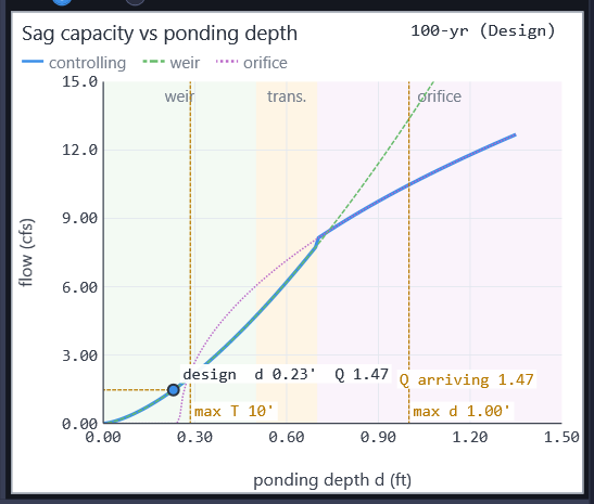
Selecting a structure also highlights it in Civil 3D, and zooms the viewport to it when Zoom to selection is enabled in View settings, the same setting the Storm Drain tab's pipe selection honors.
Switching to the Inlet tab also follows whatever pipe is selected on the Storm Drain tab: its upstream structure is auto-selected in the rail, when the rail lists it, so checking a pipe's spread takes one tab click. Select the pipe on Storm Drain, then click Inlet. It's a no-op when the Storm Drain tab has no selection, or when the upstream node isn't an inlet candidate (filtered out per above, or hidden by the alignment filter).
How It Works
HydraStorm rates inlets so that carryover is always delivered before the receiving inlet is rated. That follows the gutter, not the pipes: an inlet may bypass to one that sits upstream in the pipe network (the grade inlets on the leg a trunk leaves a sag by carry over downhill to that sag, and a parking lot rises and falls along one run), and HydraStorm delivers it. Only a genuine loop, meaning two inlets bypassing to each other, is refused. At each inlet the calculation follows these steps:
- Accumulate gutter flow. The total gutter flow at the inlet is the sum of the local basin flow (from the assigned drainage area) and any bypass flow arriving from upstream inlets.
- Compute spread and depth. Manning's equation for the gutter cross-section determines the flow spread width and curb depth for the total gutter flow.
- Determine capture capacity. Based on the inlet type (grate, curb opening, combination, slotted drain, drop/area, or Y-inlet), the gutter geometry, and the flow conditions, HydraStorm computes how much flow the inlet intercepts using HEC-22 methods.
- Route bypass. Flow that the inlet does not capture continues downstream to the designated bypass target inlet.
- Feed the pipe network. Captured flow enters the storm drain system at the inlet's corresponding pipe network node.
After all inlets are processed, the captured flows are accumulated through the pipe network and used for the HGL/EGL analysis.
Inlet Types
HydraStorm supports six inlet categories: Grate, Curb Opening, Combination, Slotted Drain, Drop/Area, and Y-Inlet. Each uses different hydraulic equations to compute interception capacity.
Grate Inlets
Grate inlets intercept flow through a grated opening in the gutter. Capture depends on the grate dimensions (length and width), grate type, and the velocity of flow in the gutter. Flow is divided into frontal flow (passing directly over the grate) and side flow (alongside the grate). At higher velocities, water splashes over the grate and is not captured.
HydraStorm supports the standard HEC-22 grate types:
- P 1-7/8"
- P 1-7/8-4
- P 1-1/8
- Curved Vane
- 30° Tilt Bar
- 45° Tilt Bar (2-1/4" spacing)
- 45° Tilt Bar (3-1/4" spacing)
- Reticuline
HEC-22 does not publish an opening ratio for either 45° tilt-bar variant, and both are excluded from sag (ponded) service per the manual: use them on-grade only.
Each grate type has a characteristic splash-over velocity curve that determines what fraction of frontal flow is captured at a given gutter velocity.
Curb Opening Inlets
Curb opening inlets intercept flow through a vertical opening in the curb face. Interception depends on the opening length and height. Depressed curb openings, where the gutter is lowered at the inlet, capture significantly more flow because the depression directs water into the opening. HydraStorm accounts for the depression geometry (width and depth) when computing interception length and efficiency.
Combination Inlets
Combination inlets pair a grate with a curb opening. Which policy governs how the two work together is a project/library setting, Combination Policy (see Inlet Library): HEC-22's default gives the curb a "sweeper" credit for whatever it captures ahead of the grate on grade, adds the grate's own frontal/side interception, and rates a sag as a weir on the grate perimeter with orifice flow through the combined grate and curb throat areas; the iSWM/Plano binary rule instead rates on-grade as the grate alone (no sweeper credit) and a sag as the curb opening alone, with the grate treated as fully clogged.
Slotted Drain Inlets
Slotted drain inlets use a continuous narrow slot along the gutter line. Capture depends on the slot length and width. These are commonly used where a conventional grate or curb opening would interfere with traffic or pedestrian access.
Drop / Area Inlets and Y-Inlets
Both are the Wye/Drop category, a box structure rather than a gutter opening, and HydraStorm always rates them as a sag: water ponds over the structure instead of passing it on a slope. Which of the two a library type models is its Opening style:
- Grated top (drop inlet, area inlet, yard inlet): a grate set in the top of the box. Rated as a grate in a sag: weir flow over the box perimeter P = 2(L+W), orifice flow through a stated open area. That open area is an input, not simply L×W: the built-in library entries publish the full plan area with the municipality's own clogging factor applied (the published sump method), and the panel states the ratio (e.g. "100% of the plan") so the assumption is visible instead of implicit.
- Side throats (Y-inlet): a top slab with a throat opening in each of the four faces and no grate. Rated as a curb opening on all four sides: weir flow over the throat-lip perimeter P = 2(L+W), orifice flow through A = P·h (h = throat height) with the head measured to the throat centroid. These are the same equations a curb opening uses, wrapped around a box instead of run along one curb face. A published open-area override is ignored for this style, since it would be the grated reading of a box that has no grate; the throat height is required.
Both are sized per structure rather than per library entry: the library ships one entry per family, at the smallest size the standard detail publishes, and each inlet's own plan dimensions (Opening L / Opening W, and the grate's Open Area override where it applies) are set on the property panel; see Inlet Dimensions below.
Sag vs. On-Grade
Every inlet operates in one of two hydraulic modes, depending on its location in the roadway profile.
| Mode | When It Applies | How Capacity Is Computed |
|---|---|---|
| On-Grade | Inlet is on a longitudinal slope where gutter flow moves past the inlet. | Interception depends on gutter flow velocity, spread width, and inlet dimensions. At higher velocities, splash-over reduces grate capture. Side flow interception decreases with velocity. |
| Sag (Ponding) | Inlet is at a low point where water ponds against the inlet. | Capacity is composed from weir flow (shallow depths, flow spills over the inlet perimeter) and orifice flow (greater depths, flow passes through the opening area) per the design standard's Sag Weir/Orifice Transition rule. The default takes the lesser of the two in the transition band, the published HEC-22 method; a library or project can select an alternate composition (Lesser Everywhere, Linear Blend, Monotone Envelope) instead, in which case the row's Method Reference states the departure. Sag inlets are typically more efficient because all approaching flow reaches the inlet rather than flowing past. |
Toggle sag mode per inlet using the Sag Inlet checkbox in the inlet properties. A drop/area or Y-inlet type is always a sag: water ponds over the box and enters over its perimeter regardless of the approach grade, so the checkbox is locked on for those; every other category can be toggled. When designing a sag inlet, pay close attention to the allowable ponding depth: if the depth exceeds design limits, you may need a larger inlet or multiple inlets at the sag point.
When the drawing carries projected stations and rims, HydraStorm suggests likely sag points from the street profile, with a suggestion chip above the checkbox: "Street profile: local low at Sta X+XX: likely a sag inlet." This is suggest-and-confirm, the same as the inlet-type match; nothing is applied until you click Apply on the chip. It only appears for a structure that is not already flagged as a sag, and a sag at the end of a run (a cul-de-sac, for example) is not suggested, so check those yourself.
Note: Sag inlets should be sized conservatively. Because all runoff drains to the low point, an undersized sag inlet can cause ponding that encroaches on travel lanes or exceeds the allowable spread.
Gutter Cross-Sections
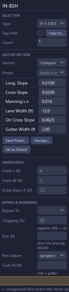
The gutter cross-section defines the shape of the roadway drainage channel. HydraStorm uses this geometry to compute flow spread, depth, and velocity using Manning's equation. Each inlet has its own gutter geometry settings.
Uniform
A constant cross-slope across the full roadway width from the crown to the curb. This is the simplest case, commonly found on residential streets. A single cross-slope value and gutter width define the section.
Composite
The gutter strip adjacent to the curb has a steeper cross-slope than the travel lane. This is the most common configuration on collector and arterial roads, where the steeper gutter slope concentrates flow near the curb and reduces spread into travel lanes. You specify both the gutter cross-slope and the roadway cross-slope, along with the gutter width.
V-Shaped
Left and right slopes meet at a V-shaped channel. Used in median ditches, some parking lot configurations, and roadside swales. You specify the left slope and right slope; there is no separate channel-width input: the section is defined entirely by the two slopes meeting at the low point.
Depressed
A depressed gutter section that creates a deeper channel near the curb to concentrate flow. The depression width and depth are specified in addition to the roadway cross-slope. This type directs more flow to the inlet and is often paired with curb opening or combination inlets.
None (Direct Ponding)
No gutter section at all: runoff ponds directly at the inlet, the honest form of a parking-lot low point, a landscape area drain, or a yard basin that used to be forced into a street section whose slopes meant nothing. An inlet on a None section always computes as a sag, no gutter fields apply, and no spread is reported: with no cross-section there is no ponded-width geometry to state, so depth is the whole check and the depth criteria are what governs. The Area Drain (No Gutter) roadway template applies this section.
Which section a type can stand in. The Section combo lists only the sections the assigned inlet type can physically be built in: a curb-opening or combination inlet needs a curbed section (Uniform, Composite, or Depressed) because its throat is in a curb face; a Y-inlet needs a curbless one (V-Shaped or None) because it stands in a landscaped low point, never against a curb; a headwall is None only, since it is a pipe entrance with no gutter at all. Grate, slotted drain, and grated drop/area inlets have no such restriction. Assigning a type whose current section doesn't apply moves the inlet to that type's default applicable section automatically and leaves a caption under the combo naming what changed and why; a pairing loaded from an older project file is left in place rather than silently moved, and instead gets a per-storm calc warning and its own row in Network Issues; see When the Assignment Breaks below.
Each inlet's gutter geometry also includes:
- Longitudinal Slope: The slope along the direction of flow in the gutter (ft/ft), entered by the designer for each inlet. HydraStorm never fills this in from the drawing: the grade at an inlet's opening is a design fact (vertical curves, grade breaks and sag approaches all fall between structures, and a parking lot has no street profile at all), so a number HydraStorm inferred would carry an authority the drawing never granted. A blank slope means an on-grade inlet is not rated at all: its whole approaching gutter flow passes uncaptured into the pipe network, the row says so, the field is framed in amber with a caption, and Network Issues names the inlet as soon as the project loads. This is the same treatment the curb opening length gets (see Inlet Dimensions below). A typed zero is a different statement, a genuinely flat gutter, and keeps its existing treatment: the on-grade equations are undefined at zero grade, so the row computes as a sag and says so. Sag-designated inlets, drop/area and Y-inlets, and inlets on a None (Direct Ponding) section don't need a longitudinal slope at all, since they pond rather than flow past; a plain manhole or an inlet whose type is unassigned or unresolvable isn't asked for one either.
- Manning's n: Roughness coefficient for the gutter surface (typically 0.013 to 0.016 for concrete gutters).
- Cross-slope(s): Transverse slope(s) defining the gutter and roadway section.
Plausibility checks, separate from "not stated." A blank longitudinal slope leaves an on-grade inlet unrated and amber, as above; that is a value never entered. Every gutter field HydraStorm actually computes with is also checked once a value is entered, for whether that value is one a real roadway could have. This catches a different mistake: a slope, cross-slope or side-slope typed as a whole-number percent instead of the ft/ft ratio these fields expect (2 for 2%, instead of 0.02) reads as a valid but absurd 200% grade, and because the error runs in the direction that shrinks computed spread and depth, a design that should fail the spread or depth criteria can pass instead, with nothing on screen to suggest why. HydraStorm warns on the row and in Network Issues on implausible entries, such as a percent typed as ft/ft, a Manning's n no gutter surface would have, a gutter or depression width far wider than a real gutter, or a depression depth entered in inches instead of feet. These are warnings, not refusals: the entered value still runs, so a legitimately steep private-site slope is computed and flagged rather than blocked. Check the value against the units the field expects before assuming the design is really as flat, as smooth, or as shallow as the row reports.
Whichever type you pick is drawn to scale for the selected inlet in the inlet section view, with the dimensions labeled.
Rim Datum and Curb Height
HydraStorm needs a gutter flowline elevation to measure ponding and the surcharge opening control from. The property panel carries a Rim (ft) field above Rim Datum: an optional per-inlet rim elevation, read under this inlet's own Rim Datum and Curb Ht exactly as the drawing's rim would be. It is stored with the inlet and never written back to the Civil 3D structure: pipe cover, HGL, and sizing keep reading the drawing's rim regardless of what's entered here. A caption under the field states where the rim actually in use came from (entered here, read from the drawing, or refused, and why; see the null-structure note below), and the resolved line beneath the pair states the gutter flowline elevation that results. Typing a rim immediately re-evaluates the street-profile suggestions that depend on it, such as the sag local-low chip.
Civil 3D structures do not agree on what their rim elevation means: most curb-inlet part families place the rim at the gutter flowline, but some firms draft curb inlets with the structure block inserted at the top of curb instead. Rim Datum states which one this structure's rim (entered or drawn) uses:
- Gutter Flowline (default): the rim IS the gutter flowline. Nothing is adjusted.
- Top of Curb: the rim is the top-of-curb elevation; the gutter flowline is derived as rim − curb height.
The Curb Ht field sets the curb height used by that subtraction (6 inches when nothing is entered anywhere in the resolver chain). Rim Datum and Curb Ht resolve like every other convention in HydraStorm: per-inlet, then project, then the active inlet library's own design criteria.
Civil 3D's rim elevation is never changed or reinterpreted, and an entered Rim is never written back to it. Pipe cover, HGL, and sizing all keep reading the drawing's raw rim exactly as before. Only the inlet side moves: ponding depth, the HGL surcharge check, and both section pictures measure from the derived gutter flowline instead.
Null structures have no usable rim. An inlet is often modeled on a null structure, a placeholder standing in for a real structure, and Civil 3D generates a null structure's rim at the pipe connection, which is an elevation at the pipe invert, not the street. HydraStorm refuses that rim on the inlet side. Capture, spread, and depth are unaffected, since none of them read an elevation, but until a rim is entered for that inlet (or a real structure is drawn in its place): the HGL surcharge check cannot run, and the row says the check was skipped rather than reporting a clean pass; the structure cutaway states it has nothing to measure the street against; and Network Issues names the inlet as soon as the project loads. Previously, every inlet on a null structure was falsely flagged as surcharged on nearly every storm, because its apparent rim sat at the pipe invert, below the water surface. Enter the actual rim elevation in the Rim (ft) field above, or replace the placeholder with a real drawn structure, to clear it.
Roadway Templates
Roadway templates are pre-configured gutter geometries that you can apply to inlets to save time during setup. Instead of entering cross-slopes, gutter widths, and Manning's n values for each inlet individually, select a template and the geometry is filled in automatically.
HydraStorm includes built-in templates for common roadway types:
- Local Street
- Collector
- Minor Arterial
- Major Arterial
- Parking Lot
- V-Ditch
- Area Drain (No Gutter): applies the None (Direct Ponding) section
You can also create custom templates with your municipality's standard roadway sections. Custom templates are saved with the project and available in the template dropdown.
The template list is filtered the same way the Section combo is: only the templates whose section the assigned inlet type can stand in are offered; see the applicability note above.
Tip
- Applying a template copies the cross-section geometry (cross-slopes, gutter width, Manning's n) but preserves the inlet's unique longitudinal slope, since that varies by location along the roadway.
- After applying a template, you can still override individual values if a particular inlet has non-standard geometry.
Bypass Flow Routing
Flow that an inlet does not capture (the bypass) continues along the gutter to the next inlet downhill. You set the bypass target for each inlet by selecting that node from the bypass target dropdown. Any node can receive bypass, whether or not it is downstream in the pipe network.
- If a bypass target is set, the uncaptured flow is added to the target inlet's total gutter flow as incoming bypass.
- If no bypass target is set, the uncaptured flow does not leave the calculation: it enters the storm drain at that inlet, so the pipes below carry the full approach flow, and the inlet is flagged undersized for it. This is often deliberate on roadway work (an inlet sized short of the approach flow on the expectation that a later connection picks the rest up somewhere in the same storm drain), and the pipe calcs account for the water either way. The same rule applies at a sag with no relief route (the pond rises and drains through the inlet) and to a target that no longer exists or sits in a gutter loop.
- Bypass chains can span multiple inlets. Flow that bypasses Inlet A routes to Inlet B, and if Inlet B also cannot capture all of it, the remainder routes to Inlet C, and so on until the flow is fully captured or reaches the end of the chain.
Auto-Suggested Bypass Targets
HydraStorm suggests a downhill bypass target for each on-grade inlet on import and reload; confirm it or change it in the dropdown like any other value. When the drawing carries projected alignment stations and rims, the suggestion follows the street profile (so set Rim Datum where it applies), not the pipe network, because gutter flow cannot cross the street the way a trunk pipe can. Without stations or rims, it falls back to the next downstream inlet in the pipe network.
An inlet with no downhill inlet along its street is left with no suggestion on purpose. HydraStorm will not guess a target across the street. That inlet reports unmatched bypass until you assign a target manually, which is the intended signal to check whether the street actually needs another inlet there. Sag inlets never receive an auto-suggested target: a sag has no downhill gutter for carryover to leave by, so any bypass target on a sag is a deliberately declared overflow path that you set yourself.
Note: Check the results for any inlets with unmatched bypass flow. This means runoff is leaving the inlet system without being captured, which may indicate that additional inlets are needed or that existing inlets are undersized. An inlet with no bypass target also gets its own line in the calculation message strip; see Inlet Warnings below.
When the Assignment Breaks
Things go stale when the drawing or the library changes underneath a project, and each one quietly moves water or mis-rates a structure. HydraStorm reports each in Network Issues as soon as the network is read, so you find out when you open the drawing rather than after a run:
- The bypass target structure was deleted. Carryover with nowhere to land is not delivered: it enters the pipes at the inlet itself, which reads undersized until a target is picked. HydraStorm remembers the name the target had, so the warning names both the inlet and the structure the carryover used to run to instead of quoting an internal id you cannot look up. Re-pick the target on the Inlet tab. Note that a structure deleted and re-drawn in Civil 3D at the same location is a new structure, so its bypass assignments break the same way.
- The inlet type is no longer in the active library (the project switched libraries, or the type was renamed or deleted). Nothing is rated at that structure: no spread, no depth, no capture. Its gutter flow, including any carryover routed to it from an inlet uphill, enters the pipe network there in full and uncaptured, which is conservative for the pipes and silent about the street. Re-assign a type, or clear the assignment if the structure is not a capture point.
- The assigned type doesn't fit the stored gutter section: a curb throat modeled against a section with no curb, a Y-inlet modeled against a street curb. The Section picker only offers sections a type can stand in going forward (see Which section a type can stand in above), but a library switch, a rename, or a project file from before this rule shipped can leave a stored pairing that no longer applies. HydraStorm computes it anyway, with nothing silently changed, and warns on every storm's row at that structure until you pick an applicable section.

Coupling with the Pipe Network
When inlet analysis is enabled, whether the pipe network carries actual inlet capture (and bypass) or the full basin runoff is set per storm, not by a project-wide switch. The control is the Route Capture column on the storm drain grid in Project Settings > Storm Drain: one checkbox per storm row. It is greyed out while inlet design is off; what was checked is kept and takes effect again when inlet design is turned back on.
- On: that storm's pipe flows route the inlet module's actual captured flow at each structure, with bypass carried downstream through the bypass chain. The storm drain system only carries what the inlets actually capture, not the full basin runoff. A more efficient inlet captures more flow, which increases pipe flows and may require larger pipes, but also means less bypass and better overall system performance.
- Off: pipes assume full interception at every structure (every basin's runoff enters the network at its structure, uncaptured). This is the conservative, conventional sizing method. The Inlet tab still rates spread and capture for that storm independently; it just doesn't feed the result into the pipe flows.
Design and check storms are set independently, so a project can route real inlet capture into the design pipe sizing while checking pipe HGL under full interception for the check storm (or vice versa).
Note: The inlet module's own storms come from the storm grid on the Inlets tab of Project Settings. Leave it empty and the inlet module simply follows the storm drain's design and check storms; give it its own rows to analyze inlet spread/capture at an independent return period (see Inlet Storm Configuration below). The line under the Storm Drain grid says which storms the inlet module is rating. The Route Capture column lives on the storm drain grid regardless; it says whether that storm drain storm's pipe flows are inlet-coupled, independent of which storm the inlet module itself is analyzing.
When the inlet storm and the pipe storm differ
Coupling never carries one storm's captured flow across to another. Each coupled storm re-rates every inlet at its own flows: at the 10-yr event an inlet captures what its geometry captures at 10-yr gutter flow, whatever storm it was sized for. So a 100-yr inlet design coupled into a 10-yr pipe design still shows on-grade carryover in the 10-yr pipes, because carryover exists at every storm on grade, and crediting the larger storm's capture would over-load the trunk at the head of the run and starve every inlet below a bypass target.
The Inlet tab keeps reporting the inlet storm's rows. When a coupled storm's carryover has nowhere to go (a sag with no assigned overflow path, or a bypass target that was deleted), the message strip names that structure and the flow that enters the pipe network at that inlet at the pipe storm (the inlet is undersized for it), since the inlet row beside it is quoting a different storm's cfs.
Tip
- When coupling is enabled, resizing an inlet or changing a gutter cross-slope triggers an automatic recalculation of both the inlet results and the pipe network HGL. The profile view updates in real time to reflect the new captured flows.
HGL Feedback and Surcharged Inlets
Once the HGL/EGL pass finishes solving a storm's pipe flows, HydraStorm closes the loop the other direction: every inlet row for that same-period storm is stamped with the structure's solved water surface and the elevation that controls whether the opening can still take water. This is a verdict, not a re-solve: it happens for every computed storm, and it never changes the pipe flows or HGL that were just published.
The water surface is the solved HGL at the structure, and an inlet on a dry lateral beneath a surcharged trunk is still caught: the lateral may show zero flow, but it is not empty, it is full of the trunk's backed-up water.
The opening control is the elevation above which the opening can no longer take water, measured from the gutter flowline, not necessarily the raw rim; for an inlet with a throat, it includes the throat height.
An inlet whose water surface stands above its opening control is surcharged for that storm: the credited interception cannot physically enter there. Two things happen, and one deliberately does not:
- The row is flagged and gets its own warning naming both elevations (the trunk HGL and the opening control), noting that plumbed direct connections may also backflow where the HGL tops the rim. On a drowned sag inlet, the warning adds that the street ponding shown is HGL-driven (HGL minus rim) and not the weir/orifice rating this row otherwise reports.
- One aggregate calc message per storm names how many inlets came up surcharged, and (see Inlet Warnings below) that same row warning also lands in the calculation message strip on its own line, so you can click straight to the drowned structure.
What does not happen: the pipe flows and HGL are never re-solved around a surcharged inlet. The published results deliberately keep the full credited capture, the loaded design envelope, because relieving a drowned inlet's contribution would report a relieved, half-empty system as the design condition and hand pipe sizing and compliance checking a network that understates what actually happens. The flag is the deliverable; relieving the system (upsizing, flattening, adding capacity downstream) is the engineer's move, not something HydraStorm proposes for you here.
A row for a storm the inlet module analyzes but that no pipe run covers (for example, an independent inlet check-storm period no alignment run was solved at) is left unstamped: blank HGL and opening control, never a false “not surcharged.” Absent means unknown here, the same convention HydraStorm uses everywhere else a value could not be computed.
Note: A surcharged inlet is a symptom, not the fix, and HydraStorm will not quietly relieve it for you. It means the downstream system is holding water high enough to drown the opening. Check pipe sizing, slope, and downstream tailwater, then re-run once you've made a change, rather than reading the reported flows as what the inlet actually passed.
The inlet module needs incremental flows. If Accumulate Flows is turned off in Project Settings, the value entered at each structure is the total arriving there rather than that structure's own contribution, usually because subtotals were brought in from an outside spreadsheet. The inlet module reads that same value as the gutter flow approaching the opening, so every inlet below the head of a run would be rated on the whole system's discharge. The calculation reports this as an error: turn accumulation back on and enter incremental flows, or turn the inlet design module off.
Inlet Warnings
Each inlet result carries its own Warnings list: spread or depth exceedance, a bypass target that no longer exists or loops back on itself, a surcharged opening (see above), no flow reaching the inlet at all, or a stale/missing inlet type. Every warning on that list now also lands as its own line in the calculation message strip at the bottom of the window, the same channel pipe messages have always used: it names the inlet by name, and clicking it switches to the Inlet tab and selects that structure in the rail. A pipe message clicked the same way still navigates the Storm Drain grid instead, since a pipe issue and an inlet issue live on different tabs. This is in addition to the row's own highlight and hover tooltip in the results grid; the message strip is what lets you review every inlet issue in the project from one list instead of scrolling the grid looking for highlighted rows.
Where HydraStorm also publishes an aggregate line (for example, the surcharge count described above), both appear: the aggregate tells you how many inlets have a problem at a glance, and the individual message for each one is what you click to go fix it.
The storm banner atop the Inlet tab carries its own shortcut to the same information: an "N failing" chip, visible whenever any inlet row in the current review storm carries a warning or a failed criterion (spread, depth, surcharge, or bypass). Click it to filter the results grid down to just those rows; click it again to show all inlets. The count itself is always judged on the full, unfiltered set, so toggling the filter narrows what the grid shows without changing what the chip says.
Clogging Factors
Clogging factors reduce an inlet's effective capture area to account for debris accumulation over time. Clogging is entered as a percent of the opening assumed blocked: 0 means no clogging (full capacity), 50 means half the inlet area is assumed blocked.
Clogging factors can be set at three levels. The highest-priority level that has a value wins:
- Per-inlet override: Set in the Clogging field of the inlet property panel (Bypass & Overrides section) on the Inlet tab. Overrides all other levels. Use this when a specific inlet is in a location prone to heavy debris (e.g., near trees or construction areas).
- Per-inlet-type in the inlet library: Set on the inlet type definition in the inlet library. Applies to all inlets of that type unless overridden at the inlet level.
- Per-category default in the inlet library's design criteria: Each inlet library carries default clogging factors per inlet category, entered as Grate Clogging (%), Curb Opening Clogging (%), Combination Clogging (%), Slotted Drain Clogging (%) and Drop / Y-Inlet Clogging (%). Applies to all inlets of that category unless overridden at the type or inlet level.
If no level states a value, HydraStorm falls back to its own per-category figure: 50% for grates and combination inlets, 10% for curb openings and slotted drains, and none for headwalls. A drop or Y-inlet with no Drop / Y-Inlet Clogging (%) stated follows the grate figure when its opening is a grated top, and clogs nothing when it is a side-throat box, so a library that means to clog a drop inlet must say so on that row.
That third level is skipped for an inlet type whose clogging basis is PreReduced: its stored opening geometry is already clogging-reduced at the source (the TxDOT Fort Worth District grates are the shipped example), so the category default would clog it a second time. Those types resolve to 0 by default unless a per-inlet or per-type factor is explicitly set, in which case HydraStorm applies it and warns that the opening is being clogged twice.
Because a default is a real reduction, the Clogging (%) box never leaves one unstated. Left empty, the box shows the percent that actually runs in grey, and the line beneath it names the level that supplied it: entered on this inlet, stamped on the inlet type, the library's own name for a category default, the type's geometry is already clogging-reduced, or HydraStorm default when nothing else stated one. Type a number to override it; clear the box to hand the inlet back to whatever level was answering before. An empty box therefore means "inherited", never "no clogging": check the line below it before concluding an inlet is being rated at full bore.
At a sag, HydraStorm reports the effect of clogging alongside its cause. The Depth column above is the CLOGGED equilibrium: the ponding the depth/spread criteria are judged against, using whichever clogging factor resolved from the chain above. Wherever a clogging factor actually applies (per-inlet, per-type, or per-category, meaning anything above 0 on either leg of a combination inlet), HydraStorm also solves the same equilibrium with clogging zeroed on both legs and reports it as Ponding (Unclogged), a hidden Excel export column (see Exporting Inlet Results below). This is a Fort Worth-style dual statement (§3.8.3.2 and kin): the gap between the two depths shows how much of the reported ponding is clogging allowance and how much is the opening's own capacity at full bore. It's blank on grade, since an on-grade inlet doesn't pond to an equilibrium, and blank when no clogging factor applies, since there's nothing to separate out.
Note: Many municipalities require minimum clogging factors in their design standards. Check your local requirements; common values are 25–50% for grate inlets and 10–25% for curb openings.
Inlet Storm Configuration
Inlets can be analyzed using a different storm return period than the pipe network. For example, you might size pipes for a 25-year storm but check that inlet spread meets roadway criteria for a 100-year storm. A banner across the top of the Inlet tab always states which storms the module is modeling and how captured flows link to the storm drain design, for example:
By default, the inlet module simply follows the storm drain's design and check storms. To give inlets an independent return period (e.g. checking spread at a storm different from the one pipes are sized for), set the inlet design and/or check return period on the Inlets tab of Project Settings (its storm grid shows once inlet design is enabled). The Storm Events... button on the right side of the banner opens this settings page directly.
On the Inlet tab the toolbar's Storm selector lists the inlet module's storms: its design storm, its check storm when check results exist, and each Analysis storm, each at the inlet module's own return period. The rows you see are the ones rated at the storm the selector names, never a storm drain storm that happens to share a role.
Analysis storms
An inlet storm with the Analysis role is rated and reported, but not judged. Spread, depth at the curb, gutter velocity, captured flow, bypass, efficiency, the length needed for full capture, and a sag inlet's ponding depth and weir/orifice flows are all computed at that storm. What is left out is anything measured against an allowance: the allowable spread and depth, the spread and depth warnings, the OK/CHECK column, capacity at the allowance, sizing suggestions, the failing count, and the allowance lines on the section and cutaway. The allowances you set are written for the design and check storms, so a 100-year analysis storm is never failed against a 10-year spread limit. Use the check storm when a second storm must be judged.
Each Analysis storm gets its own Inlet Calcs (N-yr) sheet in the workbook and its own set of drafted inlet schedules, titled "Analysis, Report Only". A storm drain Analysis storm with Route Capture checked routes capture into its pipes the same way, without judging its inlets.

Note: In the rational method, an independent inlet storm period needs IDF data loaded; that is what lets HydraStorm re-derive intensity at a different return period. Without it the banner warns and inlet calculations are skipped.
In Peak Flow Only mode nothing is re-derived, because flows are entered per storm: the inlet storm simply has its own value at each structure, and the LOCAL FLOW box on this tab edits that storm. If a structure has a flow entered for the storm drain's design storm but none for a different inlet storm, the inlet computes on 0 cfs and says so in a warning on its result row: the design storm's Q is a different storm's number and is never substituted for it.
An inlet storm that shares its return period with a storm drain storm reuses that run only when the role matches too. A 25-year inlet design storm is not the same analysis as a 25-year storm drain check storm: the check storm can carry its own allowable spread and depth, so each gets its own run and is judged against its own criteria.
Local Flow
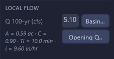
The LOCAL FLOW section of the inlet property panel, above FLOW SUMMARY, shows the gutter flow arriving at the selected inlet from its own drainage area (before any upstream bypass is added). Each row is labeled with the storm it represents, e.g. "Q 100-yr (cfs)"; a second row appears for the check storm when one is enabled.
The labels name the storms the inlet module models. When the inlet design storm follows the storm drain design storm (the default), that is the same storm, so the box is literally the Storm Drain grid's Q column for that structure. When the inlet storm is set independently, the box edits the inlet storm's own value and the caption underneath says which storm the Storm Drain grid is showing instead.
Where this flow comes from, and whether you can type into it, depends on the project's hydrology mode:
| Hydrology Mode | Local Flow Behavior |
|---|---|
| Peak Flow Only | The Q box is directly editable. It is the same value as the Storm Drain grid's Q column for that structure: editing either one updates both. |
| Manual (rational method) | Q is computed from the inlet's drainage basin (Q = C·i·A). A caption beneath the box shows the breakdown: area, C, inlet time, intensity, and the frequency adjustment factor (Cf) when one applies. A Basin... button opens the drainage basin editor. |
| HydraLink | Q is computed from the imported basin. An Info... button opens the same dialog read-only, including the contributing basins imported from HydraLink. |
There is no manual override of a computed flow: inlet design and storm drain design always use the same flow for a given structure, whether that flow is typed in directly or computed from a basin.
Drainage Basin Dialog
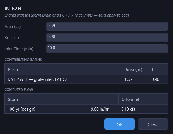
Clicking Basin... (or Info... in HydraLink mode) opens the drainage basin behind the selected inlet's local flow. In Manual mode you can edit:
- Area (ac): drainage area to this inlet. Leave blank for no basin (zero local flow).
- Runoff C: leave blank to use the project default runoff coefficient.
- Inlet Time (min): time of concentration to this inlet. Leave blank to use the project default.
A live Computed Flow table updates as you type, showing the intensity and resulting Q for each configured storm. These are the same basin values as the Storm Drain grid's C / A / Tc columns: there is one basin per structure, shared by both the Storm Drain tab and the Inlet tab, so an edit in either place is reflected in the other.
In HydraLink mode the dialog is read-only and shows a Contributing Basins table listing the HydraLink basins that feed this inlet's imported flow.
Inlet Dimensions
An inlet type in the library carries the size of a standard detail. The DIMENSIONS section of the property panel carries the size this inlet is drawn at (a 15-ft throat where the detail says 10 ft, a 2×3 grate where the detail says 2×4) without cloning the library entry:
- Grate L / Grate W (ft): grate and combination inlets. Length runs parallel to the gutter; width runs normal to the curb and also sets the frontal-flow ratio Eo.
- Opening L (ft): curb-opening and combination inlets (the curb throat), or a slotted drain's slot length.
- Opening L / Opening W (ft): the box's two plan dimensions, for drop/area and Y-inlets (Wye/Drop category). The weir perimeter and clear opening area are re-derived from the new dimensions, so a smaller box cannot keep a larger one's capacity.
- Open Area (sf): grated-top drop/area inlets only. The grate's clear opening for sag orifice flow. Blank scales the library type's stated area to this inlet's L×W.
- Count: the number of identical, side-by-side ganged units at this structure. Count multiplies the opening, and the rating curve and sizing suggestion both account for it.
- Max Ponding (ft): in the property panel's Bypass & Overrides section, the deepest ponding allowed at this inlet. It never changes the computed depth: the water surface always follows the flow (the solved equilibrium at a sag, the depth at the curb on grade). It is the allowance the row is judged against for this structure, overriding the library/project maximum, and it draws as the max d line on the rating chart. When the design flow ponds deeper than it, the row warns so the design can be addressed. Leave blank to judge on the library/project allowance.
Every dimension a manufacturer's sheet or a standard detail publishes for the assigned type can also be set per structure, the same way as Grate L/W and Opening L above, since a private-site inlet routinely runs a different precast unit than the municipal detail the library entry documents:
- Throat H (ft), curb-opening and combination inlets: the vertical clear opening at the curb face. Sets the sag orifice area and both weir/orifice regime bounds. Blank uses the library type's height.
- Depression a (ft), curb-opening and combination inlets: the local gutter depression depth at the opening. Zero is a value here, not "blank": it states a flush (undepressed) throat even where the library detail is recessed, and turns off the depression's credit accordingly. Leave the field blank, rather than typing 0, to fall back to the library's own depression.
- Depression W (ft), curb-opening and combination inlets: the width of the depression pan the throat sits in.
- Slot W (ft), slotted drains: the width of the slot opening (the slot length rides the shared Opening L field above).
- Throat H (ft), side-throat boxes: a Y-inlet's throat height, required for that opening style, which sets its orifice area and the weir/orifice handover. Not read on a grated-top drop inlet, which uses Open Area instead.
Every one of these is optional. Leave a box blank and the section view's INPUTS legend states the value that actually ran in its place (the symbol on the drawing, the panel field it came from, and whether it was entered on this structure or inherited from the library type), so a reviewer can match each dimension on the picture straight to the shop sheet, whichever supplier it is. The DIMENSIONS panel itself shows a blank field's inherited value in grey rather than leaving it looking empty.
One library entry per curb detail, in every length it is published in. A standard curb inlet detail comes in a set of sizes (5, 10, 15 and 20 ft is the common run), and length is simply an input to the interception equations, so those are not four different inlets. The library carries one entry for the detail and lists the sizes it is published in; Opening L is a drop-down of exactly those sizes, and a one-off length the detail does not come in can still be typed. What separates one library entry from another is something the equations treat differently: a different throat height, a different depression, a recessed versus a flush detail.
Auto-matching is unchanged by this. A part description that names a size, such as CI-15 or I-CO(FTW)-10'-5"CURB, still resolves to that size: the suggestion names the length alongside the type, and accepting it sets both. A description that names only the detail sets no length, and a curb opening is not rated until a length is entered: the library's published size never stands in for the one built at this structure. While the field is blank it is framed in orange, the row and Network Issues say the inlet is unrated (its whole gutter flow enters the pipe network uncaptured), and a length the part description names is offered as a suggestion under the field; click Apply to confirm it.
Leave a grate, curb, slot or drop-inlet box blank to use the library type's value (the curb opening length is required; see above). Overriding a size never changes the type: the bar pattern that fixes splash-over velocity, the weir and orifice coefficients, and the clogging allowance all still come from the library entry. Where the library publishes an explicit clear opening area and weir perimeter for a grate, both follow the new dimensions, so a smaller sag grate cannot keep a larger grate's capacity.
Flow Through the Inlet Opening
Some of a structure's runoff can enter without passing the inlet opening: a roof leader, an area drain, a yard-drain stub. The Opening Q... button in the LOCAL FLOW section states how much of the structure's flow reaches the opening, per storm; the remainder is treated as entering the structure directly. Direct flow always gets in and never bypasses to the next inlet, so it rides outside the interception calculation entirely.
This is an apportionment, never a total. The two figures always add to the structure's Q, which stays the value the Storm Drain tab states; an entry above the arriving flow is reduced to it and flagged, rather than raising the total. Leave a storm's cell blank, or use Use Drainage Areas, to fall back to the area-based split set per basin in the Drainage Basin dialog; with neither, everything reaches the opening.
The stated flow governs only the storm it names. A roof leader's share of a bigger storm is not the same fraction, so each storm is stated on its own.
Section View and Structure Cutaway
Selecting an inlet draws it twice in the design console, stacked: a section looking across the gutter, and a structure cutaway looking along the pipe. They measure perpendicular things: spread across the street versus depth down into the structure, so each gets its own scale rather than forcing one drawing to serve both.
Section View
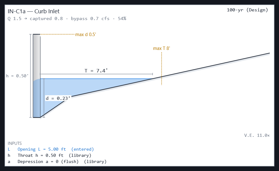
The section draws the curb as a body with the inlet opening cut through it (a curb throat notch with water standing in it, or grate bars), the gutter geometry (uniform, composite, V-shaped, depressed, or none), and the computed water surface. The water is drawn at the depth the street actually experiences: the computed gutter depth for an on-grade inlet, or the solved equilibrium ponding depth for a sag inlet. Dimension callouts label the spread (T) and curb depth (d), and dashed markers mark the governing max-spread and max-depth criteria so you can see how close the design sits to the limit at a glance. Water above the top of curb rides inside the depth chip itself rather than a separate label, shown as d = 0.58' (req) · OVER CURB, and the T/d text turns red when a limit is exceeded. A vertical exaggeration note in the corner calls out the distortion, since spread is typically much wider than curb depth.
Where the inlet type's geometry publishes a local depression (curb-opening, combination, or slotted-drain types with a stated depression depth/width, a common DFW recessed curb inlet and most TxDOT curb inlets), the pan is drawn: the pan floor is the heavy line across the depression width, the water fill stands on it, and the pavement projection above it is dashed to mark it as a datum line, not a surface. The depression is labeled directly (e.g. "a = 4″ below projection · W = 2.00'"). A pan needs a curb to hang against, so none is drawn on a V-shaped, None, or Y-inlet section.
A Y-inlet is drawn in its own landscaped low point regardless of what gutter section the node carries: the rim sits level across the box width, ground rises away from the walls at an assumed 4:1, and both side throats are shown open, with no curb, no spread, and water standing in place. This is a drawing convention only: the engine still rates spread and depth against whatever section the node is actually assigned, so a Y-inlet left on a street section is still judged on that street's spread criterion.
A None (Direct Ponding) section is drawn at an assumed 1% grade falling to the inlet from both sides, since nothing is actually built flat. A footer states the assumption ("ground drawn at assumed 1%, with no spread computed") so it is never mistaken for surveyed geometry, and no spread is dimensioned, matching the fact that HydraStorm computes no spread for a None section.
When more than one storm has a result, the other storm's water surface overlays as a dashed line for comparison.
Structure Cutaway
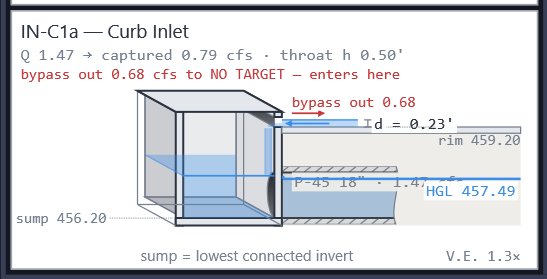
Below the section, the structure cutaway looks down the pipe: rim, sump, the outgoing barrel, the solved HGL, and the water standing above the opening. A drowned inlet reads directly off this picture: the HGL line crossing above the opening control is the same condition HGL Feedback and Surcharged Inlets reports in the results grid and the message strip, drawn instead of stated. A Y-inlet draws in its landscaped bowl here too, matching the section above. A Y-inlet's cutaway stands in the same landscaped depression as its section: ground falling to the throats at an assumed 4:1 from both sides, the pond in the bowl it makes, the footer stating the assumed grade.
Results
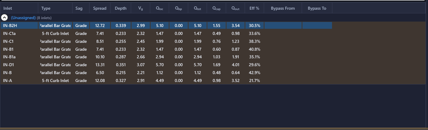
The inlet results table lays its columns out left to right the way the DFW inlet review forms do (Celina Engineering Standards Fig 3.2, Frisco §4.07.F “Inlet Calculations Table”): identity, the basin behind the local flow, the gutter flow arriving, the section and its gutter hydraulics, the curb/slot or grate terms for the opening in place, the sag weir/orifice terms, and finally what was captured and where the rest went. A per-type grid only carries the blocks that apply to that category: a curb-opening table carries no grate columns, and a grate table carries no curb-opening columns. Every value below is what the equations actually ran with, stamped by the engine, never re-read from the node or the library afterward. Use these to verify that spread, depth, and capture efficiency meet your design criteria.
| Column | Description |
|---|---|
| Alignment | The reference alignment the structure belongs to, the same grouping the Structures rail uses. |
| Station | The structure's projected station along its reference alignment, read from the same drawing-derived stations and rims as the bypass suggestion and the sag suggestion chip. Blank on a drawing without projected stations. Reads in plan-and-profile "+" notation (e.g. 12+34.56) everywhere it's shown: the results grid, the drafted CAD inlet schedule, and the Excel Inlet Calcs sheet. In the grid and the workbook the cell underneath stays a plain station number, so sorting or filtering the column orders by station rather than by the displayed text; the drafted schedule's column is fixed text in the row order the table was built in. The same station also orders rows within each inlet CAD table and the Excel sheet, by alignment, then station (see Exporting Inlet Results below). |
| A (ac): drainage area | Drainage area assigned to this structure, the incremental basin the local flow was priced from. Rational hydrology modes only (Manual or HydraLink); absent under Peak Flow Only or a HydraLink fixed-flow import, the same rule the Storm Drain and Culvert grids apply to their own C/A/Tc columns. Editable in Manual hydrology mode: double-click the cell (or press F2) and type; it is the same value as the Storm Drain grid's A column, and the edit is undoable. |
| C: runoff coefficient | Runoff coefficient the local flow ran with: the entered value, or the project default where none was entered (the hydrology walk's aggregate warning names those nodes). Rational hydrology modes only. Editable in Manual hydrology mode: an emptied cell reverts to the project default. A C typed on a structure with no drainage area is kept but prices no flow, so the cell stays blank until an area is entered. |
| T_c (min): inlet time | Inlet time the local intensity was read at, after the project's minimum-Tc floor. Rational hydrology modes only. Editable in Manual hydrology mode: an emptied cell reverts to the project default; a value entered under the floor is kept as entered and shown floored. |
| i (in/hr): intensity | Rainfall intensity at Tc for this row's storm. Rational hydrology modes only. |
| C_f: frequency factor | Frequency adjustment factor on the local flow for this storm (1.00 where none applies): Q_loc = C_f · C · i · A. Rational hydrology modes only. |
| Q_loc (cfs) | Local basin flow, the runoff contributed by the drainage area assigned directly to this inlet. |
| Q_bp (cfs) | Incoming bypass flow from upstream inlets that were unable to capture all of their gutter flow. |
| Q_tot (cfs) | Total gutter flow at the inlet (Q_loc + Q_bp). This is the flow the inlet must handle. |
| S (ft/ft): longitudinal slope | The longitudinal gutter slope the on-grade equations actually ran with. Blank at a sag, since ponding does not consult the longitudinal slope. |
| S_x (ft/ft): cross slope | Roadway cross slope; on a V-shaped section, the equivalent slope the hydraulics ran on. |
| n: gutter Manning's n | Manning's roughness of the gutter the spread was computed with. |
| Q_street (cfs): street capacity | The approach gutter's Manning conveyance at the allowance: this section, at this slope, at the allowable spread or the spread the allowable depth reaches, whichever is narrower. Compare to Q_tot to see how much reserve the gutter itself has left. On grade only; blank where no allowance resolves. |
| Spread (ft) | Gutter flow spread width, the distance water extends from the curb into the roadway. Check this against your municipality's maximum allowable spread. On a sag row, the spread describes the SAME water surface the row's depth and depth criterion are judged against (the deeper of the solved equilibrium ponding and a user-entered evaluation depth, see Depth, below), so the two numbers on one row can no longer describe two different water surfaces. |
| Depth (ft) | Water depth at the curb face. For sag inlets, this is the equilibrium ponding depth the engine solves (inflow balances capacity), always flow-based; the per-inlet Max Ponding entry is an allowance and never moves it. Both the reported spread and the depth criterion check use this same depth. Where a clogging factor applies, this is the CLOGGED equilibrium: the ponding the design criteria are judged against; see Clogging Factors below for the unclogged companion value. |
| V_g (ft/s) | Gutter flow velocity. Higher velocities reduce grate capture efficiency due to splash-over. |
| E_o: frontal flow ratio | Share of the gutter flow the interception equations act on: in front of the grate (grate and combination legs), or inside the depressed width S_e was built from (curb opening / slotted drain; blank where the approach carries no depression). See Hand-Check Values below for the full reproducibility formula. |
| S'_w (ft/ft): depression slope | The depressed width's extra cross slope relative to the pavement (a/W) that the equivalent slope was built from: S_e = S_x + S'_w · E_o (on a combination inlet, E_oc, the sweeper curb leg's own ratio). Blank where no depression ran. |
| E_oc: sweeper Eo | Combination inlets only. The sweeper curb leg's own Eo: the depressed-section ratio its S_e was built from, which is not the grate leg's Eo beside it (a different width at a different flow). S_e reconciles with this one. A curb opening's own Eo is the Eo column. |
| W (ft): depression width | The depressed width E_o was evaluated over: the inlet's local depression, or the continuous gutter's where the section carries one. |
| a (ft): depression depth | The depression depth over W. |
| S_e: equivalent cross slope | The cross slope L_T is computed from, including the depression. See Hand-Check Values below for the full reproducibility formula. |
| L_T (ft): length for total interception | The curb-opening or slot length that would capture 100% of the gutter flow. See Hand-Check Values below. |
| L_req (ft) | Opening length required, beside the length actually in place (L, below): the number a municipal review form calls "length required" next to "length provided". On grade this is L_T, the length that would intercept 100% of the approaching flow. At a sag it is the total length over all units, like L, whose ponding lands on the allowable depth, or on the depth at which the allowable spread is reached, whichever governs. Ganged units share one weir and one orifice, so that total is the same however many units carry it. Curb-opening and slotted-drain rows carry it on both paths; a combination row carries it only on grade, for the curb leg's own contribution. Blank for grate-only, drop/area and Y-inlet rows, since none of them are rated by an opening length. |
| L (ft): length provided | Opening length actually in place, all units: curb-opening length × count, or slot length × count (Opening L on the property panel is one unit). Compare to L_req. |
| L_g (ft): grate length | Grate length parallel to the gutter, all units (length × count), the length the side-flow ratio R_s runs on. |
| W_g (ft): grate width | Grate width perpendicular to the curb, per unit. |
| R_f: frontal interception ratio | Fraction of frontal flow the grate actually intercepts after splash-over. See Hand-Check Values below. |
| R_s: side interception ratio | Fraction of side flow the grate intercepts. See Hand-Check Values below. |
| Q_fr (cfs) | Frontal flow intercepted by the grate. Grate and combination inlets only; blank for other categories. |
| Q_side (cfs) | Side flow intercepted by the grate, outside the frontal prism. Grate and combination inlets only. |
| V_spl (ft/s) | Splash-over velocity for this row's grate type. Above it, frontal flow starts skipping the grate uncaptured. Grate and combination inlets only. |
| P (ft): weir perimeter | Weir perimeter the sag equations ran with, all units, after clogging: the "length provided" of a wye/drop inlet. Sag rows only. |
| A_o (sf): orifice area | Orifice area the sag equations ran with, all units, after clogging. Sag rows only. |
| d_req (ft) | The solved equilibrium ponding depth (inflow balances capacity) at a sag, the same value the Depth column reports there, kept as its own column for the hidden export chain. Sag rows only. |
| Q_weir (cfs) | Weir-leg capacity at the ponding depth, one of the two legs the sag transition rule composes into the reported capacity. Sag rows only. |
| Q_orif (cfs) | Orifice-leg capacity at the ponding depth, the other leg of the sag transition rule. Sag rows only. |
| Q_allow (cfs): inlet capacity | The sag inlet's capacity at its allowance: the controlling weir/orifice flow at the allowable ponding depth, or at the depth the allowable spread is reached, whichever is lower, on the same rule the row was rated with. Compare to Q_tot. Sag rows only; on grade the same question is asked as L_req against L. |
| Q_cap (cfs) | Flow captured by the inlet and directed into the pipe network. |
| Q_dir (cfs) | Local runoff entering the structure directly (a roof leader or yard drain, see Flow Through the Inlet Opening above) instead of through the inlet opening. Never bypasses. Only appears when a flow split is assigned to this inlet. |
| Q_in (cfs) | Total flow entering the pipe system at this structure: Q_cap + Q_dir. Only appears alongside Q_dir. |
| Q_out (cfs) | Bypass flow that continues downstream to the next inlet (Q_tot - Q_cap). |
| Eff % | Capture efficiency (Q_cap / Q_tot x 100). A 100% efficient inlet captures all approaching flow. Sag inlets typically approach 100% when properly sized. |
| Bypass From | The upstream inlets that bypass to this node, if any. |
| Bypass To | The downstream inlet this row's uncaptured flow routes to; see Bypass Flow Routing above. |
| Surcharged | Not a dedicated column in this grid: when the storm's solved water surface drowns an inlet's opening (see HGL Feedback and Surcharged Inlets above), the row is flagged in its warnings and highlighted the same way any other inlet warning is. Hover the row for the message, which names the trunk HGL and the opening control elevation, or find it in the calculation message strip. This is a verdict only: Q_cap and the other flow columns are unchanged by it, since HydraStorm never re-solves the pipe network around a surcharged inlet. Blank/unhighlighted does not always mean clear; a row for a storm no pipe run covers is never stamped either way. The Excel export can carry this as its own literal Surcharged ("YES"/blank) column and a solved Structure HGL column (see Exporting Inlet Results below), both hidden by default. |
What the grid does not reproduce from those municipal forms: the sag two-side split (a percent/cfs figure per side of the box), since HydraStorm carries one arriving flow per node; a right-of-way capacity figure, since no right-of-way section is modeled; the half-approach-slope reading of S at a sag (S is blank there, above, because ponding does not consult the longitudinal slope); and a distinct on-grade "inlet capacity" number, since on grade, L_req against L asks the same question stated in length rather than in flow.
Hand-Check Values
Alongside the flow and capacity numbers, HydraStorm retains the intermediate values a plan reviewer recomputes by hand before accepting a row, instead of discarding them once the interception equation runs. These ride with the same result that produces the row's Eff %, so the reported efficiency can be reproduced directly rather than taken on faith. Eo, Rf, Rs, Se and LT now show on the Inlet tab's results grid by default, in the positions listed under Results above: the values the DFW inlet forms carry alongside the flow columns. The rest of the reviewer's block below (clogging applied, the allowable spread/depth a row was judged against, Pass/Fail, Surcharged, Structure HGL, and Ponding (Unclogged)) stays hidden until you turn it on from the storm banner's Columns… button, which drives this grid, the Excel export and the drafted CAD schedules together; see Exporting Inlet Results below.
| Value | Applies To | Description |
|---|---|---|
| Eo: frontal flow ratio | Grate, Combination, Curb, Slotted | On a grate or combination inlet, the share of total gutter flow carried in the prism directly in front of the grate, from the grate width and the gutter section. On a curb opening or slotted drain, the same ratio computed for the depressed width Se was built from; blank where the approach carries no depression. |
| Gutter Section | All categories | The gutter cross-section type this row was rated in (Uniform, Composite, V-Shaped, Depressed, or None), useful for spotting a section mismatch when comparing rows across a run. |
| Rf: frontal interception ratio | Grate, Combination | Fraction of frontal flow the grate actually intercepts after splash-over at the gutter velocity (1.0 below the grate's splash-over velocity, falling off above it). |
| Rs: side interception ratio | Grate, Combination | Fraction of side flow (the flow outside the frontal prism) the grate intercepts, from the grate length, gutter velocity, and cross slope. |
| LT: length for total interception | Curb Opening, Slotted Drain | The curb-opening or slot length that would capture 100% of the gutter flow, per HEC-22's LT equation. Combination rows carry this only when the curb leg is doing HEC-22's independent curb calculation, not a curb-only-in-sag substitution. |
| Se: equivalent cross slope | Curb Opening, Slotted Drain | The cross slope LT is computed from: the gutter's actual cross slope augmented by the depression, where the geometry has one. |
| Clogging factor applied | All categories | The clogging factor the equations actually ran with, after resolving the per-inlet override / library type / library category default chain described in Clogging Factors above. A combination inlet reports the curb leg's clogging separately where it differs from the grate leg's, including in a sag where the library's combination policy treats the grate as fully clogged and rates the curb opening alone (the iSWM/Plano binary rule, as opposed to HEC-22's sweeper-credit model, a policy set per design standard, not per inlet). |
| Allowable spread / depth | All categories | The spread and depth criteria this row was actually judged against, resolved from the project or inlet library: the same numbers behind Exceeds Spread Limit / Exceeds Depth Limit. Blank when no criterion is configured for that inlet. |
| Method reference | All categories | A short, honest citation of which method actually produced the capture on this row, for example "HEC-22 grate on grade", "HEC-22 curb opening on grade (LT/Se)", "HEC-22 sag weir/orifice", or "Curb-only in sag (iSWM/Plano combination policy)" when the project's combination policy zeroes the grate leg in a sump. This is what tells you, on a combination inlet, which of the two policies (HEC-22's sweeper-credit model or the binary on-grade/sag rule) actually governed the row. |
| Ponding (Unclogged) (ft) | Sag only | See Clogging Factors above. The equilibrium ponding depth the same inlet would need with clogging zeroed on both legs, alongside the reported (clogged) Depth the criteria are judged against: a Fort Worth-style dual statement separating clogging allowance from opening capacity. Blank on grade and blank when no clogging factor applies. |
The two reproducibility formulas these values support:
where CF is the clogging factor applied and L is the inlet's own opening length. Multiplying either result by Q_tot reproduces Q_cap.
Tip
- Sort the results table by Spread or Eff % to quickly identify inlets that may need attention: wide spread or low efficiency often indicates an undersized inlet or high bypass accumulation.
- Rows with spread exceeding the design limit or efficiency below a threshold are highlighted, making it easy to spot problem areas at a glance.
Exporting Inlet Results
The Excel export (Output → Export > Excel Workbook..., see Excel Export) writes an Inlet Summary sheet and an Inlet Calcs sheet whenever inlet design is enabled and the calculation produced inlet results.
Inlet Summary is written first: a per-alignment-run rollup of runoff, captured, carryover, and unrouted flow (carryover with no delivered target, which enters the pipes at the undersized inlet rather than leaving) plus a project total, an exception list quoting every engine warning verbatim (never paraphrased), and an inlet-type schedule (locations versus ganged units). Its allowable-spread/depth figures are read off each row's own judged allowance (the check storm's own criterion channel or a library override, when either applies), never restated from the project setting, so the summary can't quote a number a row was never actually judged against.
Inlet Calcs carries the row-level detail. Rows are grouped by alignment and, within each group, ordered by Station: the same order the drafted CAD inlet tables use, and for the same reason, since a reviewer reading down the sheet reads down the street. A structure with no resolved station (an unstationed drawing) sorts to the end of its group. Each alignment's block ends with a run-ledger footer (runoff, carryover in, captured, carryover out, unrouted, and the in = out check), so the gutter accounting for that run closes in the workbook the same way it does on screen.
The sheet carries live formulas: edit an input on a row (C, i, A, a slope, an opening length, a coefficient) and the numbers after it on that row recompute, from local Q and carryover in through the gutter and opening hydraulics to bypass out, efficiency and the OK/CHECK verdict. Spreads, the section and opening inputs, the allowances and the Warnings text stay HydraStorm values, since spread on a depressed, composite or V gutter section has no closed-form equation for a formula to restate; a few other cells (a sag's blended weir/orifice transition, a combination inlet in a sag, a grate's Eo on a V section, a combination inlet's curb credit) are marked italic for the same reason. See Excel Export for the full list. The drafted CAD schedules and this tab's grid stay plain values.
Whenever the calculation produces check-storm inlet results, the workbook also gets an Inlet Calcs (Check) sheet, built the same way from the check-storm rows, and the drafted CAD inlet schedules get a matching check-storm set under the identical rule, so the drawing and the workbook can never disagree about which storms were reported. Both are added automatically; there is nothing to turn on.
Which columns the sheet and the drafted tables carry, and in what order, is controlled by an inlet export layout: the inlet module's equivalent of the storm-drain Excel export's column layout, and the same list the Inlet tab's own results grid draws from. The built-in default keeps every legacy "Inlet Calcs" column visible in its original order (Inlet, Type, Category, Sag/Grade, Count, Spread, Depth at Curb, Gutter Velocity, Local/Bypass/Total/Captured/Bypass Out Q, Efficiency, Bypass To, Warnings) plus Station, so an existing project's export looks unchanged apart from the one new column. The rest of the Hand-Check Values and reviewer's-block columns (Eo, Rf, Rs, LT, Se, shown on the grid by default, as noted above, but not in the workbook or drafted schedules until turned on there; clogging applied (grate and curb legs); Allowable Spread, Allowable Depth, Pass/Fail, Surcharged, Method Reference, Structure HGL, and Ponding (Unclogged)) are defined in every layout, including the built-in default, but ship hidden by default so a workbook a plan reviewer already trusts doesn't grow unfamiliar columns on its own.
The nineteen input columns behind the DFW form order (see Results above: A, C, Tc, i, Cf; Gutter Section, S, Sx, n, Q_street; S'w, W, a; L; Lg, Wg; P, Ao; Q_allow) are likewise defined in every layout but ship hidden in the Excel sheet and the drafted CAD schedules, same as the rest of the reviewer's block; existing workbooks and tables are unaffected. Turn them on the same way, from Columns…. The five basin columns (A, C, Tc, i, Cf) are written only under a rational hydrology mode even when a layout turns them on, matching the rule the Storm Drain and Culvert exports already follow for their own C/A/Tc columns.
The built-in Celina, TX (2024) and Frisco, TX (2025) inlet libraries each ship their own inlet export layout, in that City's form order with these columns turned on, so a project using either library gets the City's own inlet sheet in the workbook, the drafted schedule, and the grid, through the normal project → library → per-user → built-in resolution, so a project's own saved layout still wins over the library's.
Turn them on from the Inlet tab's storm banner: the Columns… button opens a picker that drives the results grid, the Excel sheets and the drafted CAD schedules together, one switch, one column list, saved to the project and to your per-user default. As with the storm-drain layout, a municipality can also ship its own default inlet column set alongside its inlet library, for example a jurisdiction that wants Pass/Fail and Method Reference visible on every submittal. The layout used at export (and on screen) time resolves in priority order: a layout saved on the project → the active inlet library's own layout → your per-user default → the built-in default described above.