Alignment Design Types
Each Civil 3D alignment in your drawing can be classified as a Storm Drain, a Culvert, or None. The classification determines which calculation engine processes pipes on that alignment and which set of design criteria applies.
The Three Types
| Type | Engine | Use For |
|---|---|---|
| Storm Drain | HGL/EGL pipe network analysis | Buried storm drain pipes, inlet laterals, trunk lines, manhole-to-manhole runs |
| Culvert | FHWA HDS-5 culvert analysis (inlet/outlet control) | Roadway crossings, channel crossings, headwall-to-headwall short barrel runs |
| None | (skipped) | Reference alignments not part of the drainage analysis |
Why It Matters
Storm drain and culvert hydraulics use different methods, different boundary conditions, and different design criteria:
- Storm drain: backwater HGL analysis, junction losses at structures, design storm + check storm freeboard
- Culvert: controlling headwater (max of inlet control and outlet control), HDS-5 polynomial inlet equations, tailwater boundary conditions, multi-barrel flow division
Treating a culvert as a storm drain (or vice versa) produces wrong answers. The classification ensures the correct engine handles each pipe.
Setting Alignment Types
Open Tables > Alignment Types... on the main window toolbar. Each alignment in your drawing is listed; pick the type from the dropdown. Alignment types aren't part of Project Settings; they're a network-topology fact, edited in their own table.
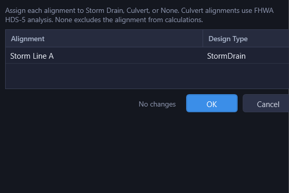
Defaults: alignments are Storm Drain until you mark them otherwise. Change to Culvert for any alignment that should be analyzed using FHWA HDS-5 methods, or None to exclude an alignment from the drainage analysis entirely.
What Each Type Produces
Storm Drain Alignments
- Pipe results in the main Results grid
- HGL/EGL profiles in the profile view
- Compliance checks against the storm drain design criteria
- Output to the Storm Calcs Excel sheet
Culvert Alignments
- Pipe results in the Culverts grid (separate from storm drain)
- Inlet control and outlet control headwater computed; controlling type and HW shown
- Tailwater boundary, outlet velocity, barrel condition, flow type: all in the grid
- Output to the Culvert Calcs Excel sheet
- Independent design and check storm return periods (different from storm drain storms)
None Alignments
No analysis runs on these alignments. Useful for survey alignments, reference centerlines, or older alignments left in the drawing for context.
Mixed Networks
A single drainage network can span multiple alignments of mixed types. A common pattern: storm drain trunk lines on one alignment, road crossings (culverts) on cross alignments, all hydraulically connected. HydraStorm correctly handles each segment with the appropriate engine and stitches results together at common nodes.
Where a culvert crossing sits below a storm drain run, the crossing's headwater seeds the storm drain's HGL at the pipe entering it, but always at the storm drain's own storm, even when the culvert module is configured with an independent return period (a common pattern: a 100-year culvert crossing under a 10-year storm drain system). The storm drain's HGL is only ever seeded by the water surface that actually coexists with its own pipe flows. See Culvert Storm Events for how independent culvert storms work.
Tip: When a single barrel transitions from storm drain to culvert (e.g., a manhole-fed pipe that daylights at a headwall), classify the alignment of the daylight portion as Culvert. The structure connecting them serves as the boundary node between the two engines.
For full culvert calculation methodology, see Culvert Analysis.