Auto Design
Auto Design sizes and grades the pipes in your network against the design criteria in Project Settings, giving you a complete proposal to review and refine. Nothing changes in your drawing until you apply it.
Scope: the Selected Alignment
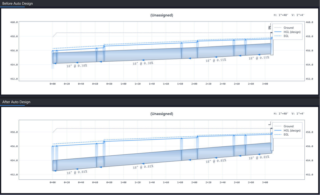
Auto Design sizes the pipes on the alignment currently shown in the profile view. Pipes on other alignments keep their existing sizes and inverts, and act as fixed hydraulic context; the sized run ties into the live HGL at the connection structure. To size a different line, switch the profile view to that alignment and run Auto Design again. When the drawing has no alignment data, the entire network is sized in one pass.
Because Auto Design never modifies pipes outside the selected alignment, a size-rule conflict at the boundary (for example, the sized run coming out larger than the existing pipe it discharges into) is reported in the calculation messages instead of silently changing the other line.
Tributaries
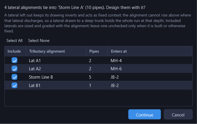
When Auto Design runs scoped to the profile view's alignment (the default scope described above), it also looks upstream for tributary alignments: pipe runs drawn on a different alignment that tie into the scoped one, including the laterals of those laterals, all the way up the tree. If any exist, the Auto Design: Tributaries dialog appears before sizing starts, one row per tributary alignment: Include, Tributary alignment, Pipes (how many), and Enters at (the scoped structure it discharges to). Select All and Select None buttons act on the whole list.
Rows are checked by default, or as you left them the last time you saw this dialog: the choice is remembered per user. A tributary you include is sized and graded together with the alignment, as part of the same run. A tributary you leave unchecked keeps its drawing inverts and acts as fixed hydraulic context like any other out-of-scope pipe: the alignment cannot rise above where that lateral discharges into it, so a lateral drawn to a deep trunk holds the entire scoped run at that depth.
The prompt appears only when at least one tributary alignment ties into the scope, and only for an alignment scope; it never appears when you've scoped to a pipe selection (see Scoping to a Selection below), because a selection scope simply treats everything outside it as fixed context, tributaries included. When tributaries are included, the run's status message names them, for example Auto Design (alignment 'Line A' + 7 tributary alignments, 33 pipes): ....
Scope-Hold Warnings
Out-of-scope pipes keep their drawing geometry and act as fixed hydraulic context (see above), so a trunk and its laterals generally can't be designed one alignment at a time and still converge: whichever one is designed second is held against the drawing inverts of the one designed first. When a scoped run (alignment or selection) is held materially below what it could otherwise achieve, by geometry outside the scope, Auto Design reports it as a Warning in the calculation messages. Small holds aren't reported, and a whole-network run never emits these, since there's no out-of-scope geometry to hold against. Both the Classic and Phased engines report it. Two forms appear, depending on which side of the tie-in is scoped:
- The scoped run's own trunk is held below its ceiling by a fixed pipe discharging into it: “'Line A' is held 9.3 ft below its own ceiling at 'Structure - (80)' by out-of-scope 'Pipe - (113)' on 'Lat A7' (drawing invert 664.86). Include that lateral in the scope or run the whole network.”
- The scoped run is itself a lateral, anchored on a fixed pipe it discharges into: “'Lat A7' anchors on the drawing invert of out-of-scope 'Pipe - (73)' on 'Line A' at 'Structure - (80)' (665.11), 8.4 ft below what the design would allow there. Design 'Line A' with its laterals first, or include it in the scope.”
Either way, the message names the way out: bring the held pipe into scope through the Tributaries prompt, or run the whole network (or the trunk together with its laterals) in one pass instead of one alignment at a time.
Scoping to a Selection
Select two or more pipes (in the profile view or the results table) before clicking Auto Design, and a scope prompt appears first: Selected pipes only (N), the default, or the entire alignment (or entire network, when the drawing has no alignment data). Choose the alignment/network option to fall back to the normal scope described above.
Sizing just a selection is useful for a surgical re-run: resizing one branch, or a handful of pipes after a change, without disturbing the rest of the alignment. Everything outside the selection keeps its current size and grade and acts as fixed hydraulic context, the same rule as alignment scoping.
The selection doesn't need to be contiguous. Disconnected groups of selected pipes are sized independently, each against its own downstream boundary condition, and a warning naming the group count appears in the calculation messages.
The chosen scope carries through the rest of the run, including the Start Elevations dialog and the downstream-lowering re-run prompt if one appears. When the run completes, the status bar reports (N selected pipes) in place of the alignment name, so you can see at a glance which scope was used.

Every Pipe Gets a Recommendation
Auto Design reviews every pipe in scope and renders a verdict on each one: confirm the existing size, upsize it, or downsize it (down to the minimum size in your settings when the flow warrants it). A pipe shown unchanged means Auto Design confirmed that size; pipes are never silently skipped or held. Dry pipes (no flow) are recommended at the minimum catalog size.
Where your criteria can't all be met at once (a shallow run with a required barrel too large to fit under the minimum cover, for example), you still get a usable recommendation, and every unmet constraint (cover, velocity, capacity, HGL clearance) is named in the calculation messages. The status bar reports how many recommendations carry unmet constraints so you know how much there is to review.
A steep pipe leaving a structure can put the water in that structure above the ground by itself. Under HEC-22 4th Ed (Table 9.7 Condition D), where the pipe leaves the structure supercritical, the structure's energy is at least the pipe's normal-depth energy, and on a steep pipe that is mostly velocity head. The Phased engine answers this by lowering the structure so the pipe leaves it at a flatter grade, before it considers a larger pipe. It keeps the shallowest structure that clears your HGL cover, and an informational row names the structure and the grade it chose.
With the Phased engine (the default) on the HGL-governed capacity basis, a proposed pipe may run under pressure, and that is reported rather than hidden. One accepted surcharge gets its own informational row. Several are gathered into a single row giving the count, the most heavily loaded pipe, and the least HGL cover among them: click it to go to that pipe, and open its detail for every pipe's own sentence. On the Gravity full-flow basis a surcharge is a defect and stays a warning on its pipe.
Pipe Size Never Decreases Downstream
Each pipe is sized for its own accumulated flow, so pipes are naturally smaller toward the headwaters. Auto Design also enforces the standard rule that a pipe leaving a structure must be at least as large as every pipe entering it. When a constraint forces one pipe larger, the change carries through the run to keep that rule satisfied, and each resulting size bump is reported in the calculation messages so you can see what drove it.
Workflow
- Assign flows: Make sure you have flows assigned at each inlet or structure, using any of the available hydrology modes.
- Set junction loss types: Assign appropriate junction loss types to each structure so the HGL calculation includes energy losses at junctions.
- Run Auto Design: Click the Auto Design button. Auto Design always establishes its own fresh baseline before sizing, so there's no separate calculate step to run first. If the run has an outfall or scope tie-in, the Start Elevations dialog appears first: confirm or override the starting inverts, then click Run Auto Design in that dialog to proceed. The suggested sizes appear in the results grid and profile view.
- Review: Inspect the proposed sizes and grades. Check for adequate cover, constructability, and any site-specific requirements Auto Design cannot account for.
- Accept or reject: Click Apply to C3D to write the new sizes to Civil 3D, or Discard to revert to the original sizes.
- Verify: After applying, HydraStorm recalculates automatically (or press F5 for an immediate refresh) so you can confirm the final HGL with the accepted pipe sizes.
Start Elevations
Before it sizes anything, Auto Design shows the Auto Design: Start Elevations dialog, with one row per starting point in the run: every outfall, and every structure where the run ties into out-of-scope pipe. Each row lists that point's Drawing Invert and an editable Start Invert the proposed profile is built up from. Leave a row at the drawing invert to keep it tracking the drawing as you edit; enter a different value to fix the proposal to a specific elevation (a required outfall elevation, for example).
Overrides are saved with the project and apply only to the starting points shown; other alignments are untouched. Use Reset to Drawing to clear every override in the dialog at once, or Cancel to abort the Auto Design run entirely; nothing is changed until you click Run Auto Design.

Sizing Storm
When multiple storms are configured, Auto Design sizes pipes to whichever storm event is selected as the Sizing Storm in Project Settings > Storm Drain, normally the design storm (e.g., the 10-year event), though a check-storm sizing basis is also available for jurisdictions that size to the check storm's capacity. The other storm still runs and appears in the results grid for verification, but doesn't drive pipe selection. The HGL Cover constraint below follows suit: whichever storm is being sized supplies its own cover requirement, either the design storm's HGL Cover (ft) setting or the project's separate check-storm HGL cover value when sizing to the check storm (that value defaults to 0.0 unless a design standard's published criteria set it).
Proposed Grades
Everything below describes the default, Auto Design Grades set to Design new grades (Project Settings > Storm Drain): Auto Design proposes a complete invert profile for the run, not just pipe sizes. It works within the cover, slope, velocity, and clearance limits you set in Project Settings, and aims for an efficient, buildable grade. The result generally reads like a profile you'd draw by hand rather than a machine minimum. Switch Auto Design Grades to Hold existing grades and Auto Design leaves every invert exactly where the drawing has it, sizing purely against the fixed grade instead: a StormCAD-style size-only check, useful when the grades were set by someone else (or another discipline) and aren't yours to move.
One thing worth recognizing in the proposal: at a real structure, an incoming pipe may ride above the match-criteria transition all the way up to its own downstream cover ceiling (a drop connection) instead of matching what it ties into. This is opt-in, off by default (Project Settings > Storm Drain > Drop Connections): turned off, every pipe holds the chained match-criteria transition exactly, and a shallow run climbs with grade instead of stepping down at a structure. Turn it on when trench-depth savings on an upstream reach are worth a plunge into the structure below: a site/cost call, not something Auto Design should decide for you by default. Max Added Drop at Structure (ft), alongside it, caps how much drop Auto Design may add above the match criteria (0 = no limit); it never limits a crown-match step you set by hand.
An efficient profile can put a run's entire drop into a single pipe wherever a shallow cover ceiling meets a fixed low point, for example a short connector plunging into a fixed outfall, or a short inlet stub above a deep junction. Auto Design leaves that grade as the ceilings and fixed points dictate, and a very steep proposed pipe gets an informational SteepGrade row recommending the alternative: a deeper inlet (or structure) at its upstream end, with how much deeper it would need to be. Nothing is moved; the choice is yours.
An optional constructability limit works alongside drop connections: Max Pipe Grade (Auto Design, 0 = none) (Project Settings > Storm Drain, ft/ft, default 0 = off). With a value set, Auto Design spreads the excess fall across the run instead of leaving it all in one steep pipe, without raising any pipe above its cover ceiling. Minimum slope is never given up to make room, and crossing clearances are respected the same as everywhere else.
Each pipe regraded this way gets an informational note naming how much of its fall moved and which pipe took it. Fall the run genuinely can't absorb stays on that pipe, which is then reported as relaxed: a warning naming the excess fall the run could not absorb, along with an informational note explaining why. This is a constructability rule, not a compliance criterion: the compliance grid doesn't judge it, and it never changes a pipe's size. Leaving it at 0 (the default) keeps the pass off and relies on the steep-grade advisory above. It runs with the Phased engine (the default); Classic does not apply this cap.
Review the proposed grades the way you'd review any first-pass profile. Anything you'd rather set by hand can be adjusted afterward with the pipe editing tools.
Downstream-Lowering Suggestions
Sometimes the minimum-slope line working up from a starting invert overshoots a minimum-cover ceiling further upstream: the run simply can't stay both at minimum slope and under minimum cover from where it starts. When that happens, Auto Design offers a lowered starting invert that resolves it, in an informational message and a prompt: accept it, and the value is saved into that outfall's Start Invert and Auto Design re-runs automatically with the lowered start. The suggestion appears only for a cover conflict that lowering the start would actually fix; a shortfall in HGL clearance, velocity, or capacity never produces one.
A pipe that outfalls at a headwall cut to grade is a special case. The surface meets the barrel at the headwall and climbs away along the cut, so the first stretch of pipe cannot hold minimum cover at any grade; nothing Auto Design proposes changes that, and lowering the outfall would only move the cut. Auto Design recognizes that reach and leaves it out of the cover constraint: the outfall pipe is graded like any other instead of being held on the minimum-slope line, no lowering is suggested for it, and cover is judged normally once the ground recovers. An informational message names how many feet were treated this way, and it becomes a warning when that reach covers an unusually large share of the pipe, because a barrel at daylight that far is more likely a ditch bottom or the wrong reference surface than a headwall. A buried outfall end that is merely short of cover is not a headwall cut and is reported as a cover shortfall. The Min Cover compliance check reads the same rule, so the grid never disagrees with the proposal.
Design Constraints
Auto Design respects the following constraints, configured in Project Settings > Storm Drain:
| Constraint | Description |
|---|---|
| Min Diameter | No pipe will be sized smaller than this value. Most jurisdictions require a minimum of 18 inches for storm drain mains. Picked from a drop-down of real sizes in the Default Circular Family (Project Settings > Storm Drain), or the first circular family in the parts list when none is set. Every pipe is held to it, whatever its family. For box sections it filters on rise rather than span. |
| Min Slope Basis | How the minimum slope floor is set for each pipe size: Fixed value applies the project's Min Pipe Slope scalar to every size (the legacy default); Velocity-based derives each size's own minimum from the slope that reaches Min Velocity flowing full (letting large trunks run flatter than small laterals, the basis municipal per-diameter minimum-slope tables are built from); Greater of both keeps the scalar as an absolute floor under the velocity-based value. The Min Slope compliance check uses the same resolver, so sizing and compliance never disagree. |
| Max Velocity (fps) | Pipes are sized so Q ÷ full-barrel area does not exceed this limit: the same basis the Max Velocity compliance check uses, and independent of the pipe's slope. This is a size constraint, not a grade limiter: a size that clears it may still be graded as steeply as cover and the other limits allow. Typical values range from 10 to 20 ft/s depending on pipe material. |
| Sizing Capacity Basis | What counts as adequate capacity when choosing a size. HGL-governed (the default) allows a size where the computed HGL still clears the required cover below grade, even if that means the pipe runs under pressure, common North Texas practice. Gravity full-flow requires Q to stay at or below the pipe's full-flow gravity capacity, so surcharge is never proposed. |
| Minimum Structure Depth | Ensures structures are deep enough by constraining the minimum depth from rim to invert. Auto Design will not size a pipe so large that it causes a structure to be shallower than this limit. Where a structure still comes in shallower than you asked for, an informational message says so and suggests lowering the downstream run, a site-specific call Auto Design leaves to you. |
| HGL Cover | Minimum clearance (ft) from the hydraulic grade line to the ground surface or structure rim: the design or check storm's own value, whichever storm is being sized (see Proposed Grades). |
| Min Crossing Clearance | Minimum vertical clearance (ft) from crossing pipes: other storm lines, or water/sewer utilities referenced through data shortcuts. See Crossing Avoidance below. |
| Cover Grade Breaks | Off by default (a TIN surface can undulate, and chasing every dip would litter a run with breaks). Turn it on to let Auto Design introduce intermediate grade breaks that follow cover along an uneven surface, instead of holding one straight grade between structures. Min Grade-Break Leg Length (ft) sets the shortest leg a break may produce. |
Crossing Avoidance
Pipe crossings detected when the network is loaded act as vertical obstacles. Auto Design routes the proposed profile clear of them by the project's Min Crossing Clearance. Your other limits still govern: a pipe never flattens below minimum slope or gives up required cover to dodge a crossing.
When no grade within those limits can clear a crossing, the recommendation stands (every pipe always gets a verdict) and a warning in the calculation messages names the crossing pipe and the clearance actually achieved. Resolve it by adjusting the run or the crossing utility, then re-run Auto Design. The result is always visible in the profile view: the red dashed ring around each crossing marks the keep-out zone the proposed profile must stay outside.
With the Phased engine, where the proposal passes under a crossing it could have passed over, and doing so lowers the run below it by a foot or more, an informational row on that pipe says how much lower the run sits and over what length, and that a structure with a drop just below the crossing would let the line pass over instead. Nothing is moved; adding the structure is your call.
Note: Crossing locations and utility elevations are scanned at network import, Refresh from CAD, project load, View > Rescan Crossings, Create Profile Views, and Output > Tables to Drawing > Crossing Table. If another discipline's design moves a crossing utility, use View > Rescan Crossings (or Refresh from CAD) to refresh crossing data before re-running Auto Design.
Mid-Run Pipe Size Changes (Splits)
Rather than carry one size along an entire run, Auto Design can propose stepping the size up partway along it by breaking the run at a pipe-size-change null structure, keeping the smaller size upstream of the break and the larger size downstream. Slopes are held between structures; a split changes where the size steps up, not your grades.
This behavior is controlled by Project Settings > Storm Drain:
| Setting | Default | Description |
|---|---|---|
| Auto Design Size Changes | Never (upsize whole run) |
Never (upsize whole run): Auto Design upsizes the entire run instead of splitting it. Prompt before adding: Auto Design computes split proposals and shows a confirmation dialog before applying any of them. Add automatically: proposals are applied to the working model without a prompt. |
| Min Split Leg Length (ft) | 20 ft | Shortest leg a split may produce. A run shorter than twice this value is never split; it's upsized whole instead. |
| Split Station Rounding (ft) | 1 ft | The break station (measured from the downstream structure) is rounded to a multiple of this value, so breaks land on round stations you can dimension. |
Pipe-to-pipe transitions during sizing, including the transition at a size-change break, follow the project's Default Match Criteria setting (Project Settings > Storm Drain): Inverts holds the invert line through the transition (the default), Centerlines splits the offset between the two pipe sizes, and Crowns lines up the pipe soffits. Under Crowns, a split may be declined where the resulting grade can't satisfy your slope limits.
The Confirmation Dialog
When Auto Design Size Changes is set to Prompt before adding and a run qualifies for a split, Auto Design shows the Auto Design: Pipe Splits dialog before any split is added to the working model. Each row lists:
- Pipe and a Proposal summary: the break station, the size kept upstream, the larger size proposed downstream, and the whole-run upsize alternative for comparison.
- Break Sta (ft): the break location, measured from the downstream structure. This is editable.
- Action: per row, choose Add size change (accept the split as proposed or as relocated), Upsize whole run (fall back to sizing the entire run at the downstream leg's size), or Skip pipe (leave it unchanged; its HGL violation stands).
- Issue: validation errors for an edited break station, described below.

You can move a proposed break station farther upstream (a larger station value) freely. Moving it closer to the downstream structure, or to a station where cover at the size-change structure would be violated, may be rejected; the reason appears in the Issue column, and clicking OK re-opens the dialog until every row's station is valid.
Note: Clicking Cancel aborts the entire Auto Design apply, not just the splits. Nothing changes in the working model, including pipes that weren't part of any split.
Applying Splits to Civil 3D
Accepted splits are written to Civil 3D automatically the next time you click Apply to C3D; there's no separate step. Applying a split breaks the drawing pipe at a new size-change null structure, leaving two pipes with the sizes and inverts of the accepted (or relocated) proposal.
The new null structure is named <pipe>-SC and the new downstream-leg pipe <pipe>-DS, based on the original pipe's name. If those names are already in use in the drawing, Civil 3D's auto-generated name is kept instead and a notice appears in the Apply messages.
The Apply to Civil 3D: Preview dialog lists every pending split (the null structure and new pipe it will create) alongside the other pending changes, before anything is written.

Note: Applying a split requires a Null Structure family in the network's active parts list (Parts List > Structures > Null Structure). If none is available, that split is left pending (you'll see a message explaining what to add) and everything else in the batch still applies. Pending splits are retried automatically on your next Apply, and they survive saving and reopening the .hsp project file.
Wyes and the Lateral Match Rule
A wye, for this rule, is any eligible structure with exactly two pipes entering and one leaving: a null structure, a healed auto-joint, or a real Civil 3D part whose description or name matches a Fitting Keyword (Project Settings > Storm Drain) as a whole word, such as "45 WYE" or "18X12 WYE". A manhole receiving a lateral is a manhole, not a wye: it's never picked up by this rule, however many pipes converge on it. A structure with three or more inlets isn't a wye either: a manufactured fitting has one lateral, so HydraStorm reports it in Network Issues instead and grades it under the ordinary Match Criteria rule.
Of the two inlets at a wye, the straight-through inlet is the trunk; the other is the lateral.
With Lateral Match at Wyes (Project Settings > Storm Drain) set to anything other than Same as network, both Auto Design engines and the multi-pipe slope tools hold the trunk at invert continuity through the structure (no crown step, no centerline step, no structure drop), the way a manufactured wye is actually cast, and match the lateral to the trunk using whichever criterion the setting names (Inverts, Centerlines, or Crowns, usually Centerlines, since that's how a manufactured wye's branch is typically cast). This is independent of the project's Default Match Criteria, which still governs every other transition in the network, and still governs the lateral too when the wye rule is off.
Same as network turns the wye rule off entirely: every incoming pipe at every structure, wye or not, follows Default Match Criteria exactly as it did before this setting existed.
Note: New projects default Lateral Match at Wyes to Centerlines. A project saved before this setting existed loads with Same as network, so no invert moves under you on open; switch it explicitly once you're ready to adopt it.
Laterals at Manholes and Other Structures
A lateral that enters a real structure (a manhole, an inlet, a junction box, anything the wye rule above does not classify) has a rule of its own: Lateral Match at Structures (Project Settings > Storm Drain). At such a structure the trunk inlet is the one that continues the main, and it keeps the ordinary Match Criteria. Every other inlet is a lateral, matched into the main by the criterion this setting names and never stepping less than the Structure Drop: with Crowns (the default for new projects) a 15" lateral into a 24" main steps down to crown-match, while a lateral the same size as the main has nothing to match and takes the drop; Centerlines works the same way on the centerline step; Inverts applies the drop alone. Twin barrels entering side by side are graded together as the trunk. A structure with three or more inlets gets one trunk and several laterals under this rule (unlike a wye, which refuses it). Where nothing in the drawing says which inlet continues the main (no reference alignments and no plan geometry), the structure is left on Match Criteria and Network Issues says so.
Same as network turns the rule off: every lateral follows Match Criteria exactly as it did before this setting existed. A project saved before it existed loads that way, so no invert moves under you on open. Both Auto Design engines and the multi-pipe slope tools read the rule; the trunk's optional drop-connection ride is unaffected by it.
See Label Fittings to have HydraStorm write manufactured-style part descriptions (e.g. 24" X 18" 45%%d WYE) onto the wyes this rule recognizes, and to see the same three-or-more-inlet and trunk-size-change conditions surfaced as Network Issues rows.
Auto Design Engine
Project Settings > Storm Drain > Auto Design Engine selects which engine does the sizing. Phased is the default: a new project starts on it, and a project saved before Phased became the default opens on it too. Nothing else in the project changes, and Classic is one pick away.
- Phased (size, then profile, then HGL): the default. It weighs the run as a whole before settling on a profile; on long runs it tends to produce steadier grades.
- Classic: the long-standing engine, still available for projects designed on it.
Both engines answer to the same design criteria, part families, match criteria, drop-connection settings and scope, and the compliance grid judges the result the same way either way. Everything on this page applies to both unless it says otherwise. Switching changes the proposals you get, not the rules they are held to.
Run Auto Design with Phased selected and the status bar reads [phased engine]. After the run, the calc-messages banner carries an Auto Design governance line naming the junctions that set the run's depth, so you can see what drove the result instead of inferring it.
Two things Phased does not do yet. With Auto Design Grades set to Hold existing grades, the run falls back to Classic and says so in the messages. Phased has no hold-grades mode. Phased also does not propose pipe splits or downstream-lowering suggestions; if you rely on either, switch to Classic.
Part Families
Auto Design picks sizes, never materials. Each pipe is sized from its own Civil 3D part family, on its own Manning's n, and keeps its shape: an HDPE pipe gets an HDPE size, an RCP pipe an RCP size, and a box stays a box. If your parts list has 18", 24", 30", and 36" RCP, an RCP pipe is sized from exactly those. The Family box on the property panel changes the selected pipe's family; it does not choose a family for the run.
To make more sizes available, add them to the parts list in your Civil 3D drawing. To change a pipe's material, change its family on the property panel before you run Auto Design.
A pipe whose family is not in the network's parts list is sized from the Default Circular Family (or Default Box Family) in Project Settings > Storm Drain, and takes that family when you apply the results. With no default set, it is sized from the first family of its shape in the parts list, and a warning asks you to set a default. A pipe whose own family has no size at or above Min Diameter is treated the same way. A pipe that no family in the parts list can size keeps its drawing size and grade, and the pipes around it are designed to it. The calc messages name every one of these pipes.
Auto Design Is a Starting Point
- Auto Design sizes pipes for capacity, velocity, and HGL cover. It does not optimize for constructability, cost, or site-specific constraints beyond what is in Project Settings.
- Always review the suggested sizes and make manual adjustments for project-specific requirements.
- After accepting an Auto Design, use the pipe editing tools (Raise/Lower, Match to Adjacent, Set Slope) to fine-tune inverts.
Note: Auto Design needs flow data to size against, so make sure flows are assigned (see Workflow above) before running it, but you don't need to trigger a calculation yourself first. Auto Design runs its own fresh baseline every time you click it.