Project Settings
The Project Settings dialog configures calculation methodology, hydrology, design criteria, and display options for your project. Open it from the Settings button in the toolbar.
The dialog has six tabs. Hydrology answers "where does runoff come from"; each module tab (Storm Drain, Culverts, Inlets) owns its own storm events and its own parameters.
| Tab | Contents |
|---|---|
| Project | Project identification and two per-user preferences. |
| Hydrology | Hydrology mode, the HydraLink link, rational-method options and defaults, and the IDF Curves sub-tab. |
| Storm Drain | Storm events for the pipe system, flow accumulation, every design parameter and compliance check, and the quantity-takeoff depth classes. |
| Culverts | Storm events for culvert-designated alignments. |
| Inlets | The inlet module on/off switch and its storm events. |
| Display | Per-quantity decimal places for grids, CAD tables, and Excel. |
Label styles are not in this dialog; picking and applying them is one action on Output ▾ > Apply Label Styles…. See Profiles & Labels.
Project Tab
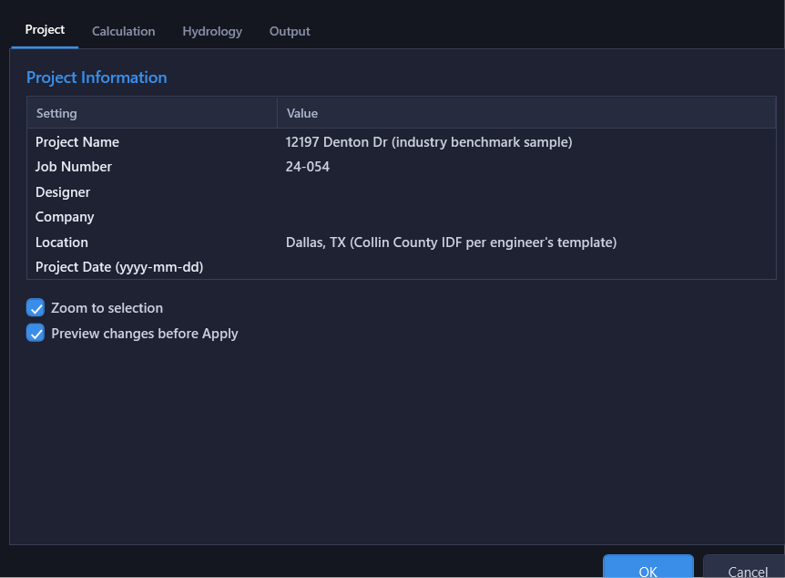
Basic project identification. These values appear on exported reports.
| Setting | Description |
|---|---|
| Project Name | Name of the project |
| Job Number | Project or job number for tracking |
| Engineer | Engineer of record |
Storm Drain Tab
Everything that governs the pipe system: which storms it is run for, how flow accumulates through it, the hydraulic calculation engine, design constraints, and pipe design criteria.
Storm Events
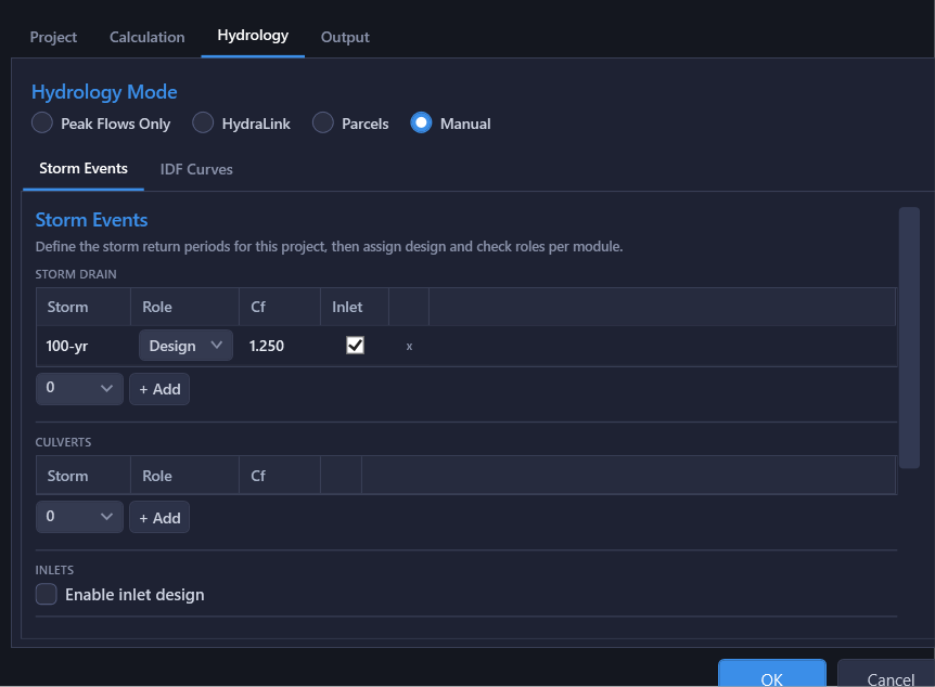
Storm return periods are configured as a small grid rather than a single design/check pair. Add as many storm events as your project needs and assign each one a role.
| Column | Description |
|---|---|
| Storm | The return period label (e.g. "10-yr"), read-only once added. |
| Role | Design, Check, or Analysis. At most one Design and one Check. |
| Cf | Read-only. The storm frequency adjustment factor this storm will be computed with, resolved from its return period. Cf is a property of the return period rather than of the module analysing it, so it is set once in the Cf table on the Hydrology tab and shown here for traceability. See Frequency Adjustment (Cf). |
| Inlet | Checkbox. When checked, this storm's captured inlet flows feed into the storm drain HGL calculation for that storm. |
This grid does not create storms: it assigns ones already declared on the Hydrology tab's Storm Events table. The combo box beneath the grid lists only project storms this module hasn't picked up yet; pick one and click + Add to assign it. The x on a row unassigns that storm from the storm drain (it stays on the project and on any other module still using it). When a Check role is assigned, a Sizing Storm radio (Design / Check) appears, controlling which storm Auto Design uses for pipe sizing.
Culverts and inlets have their own identical grids on their own tabs, so their storms and roles are independent: a municipality that sizes pipes for 10-year but checks inlet spread against 100-year declares both on the Storm Events list, then assigns the role it wants on each tab. Two things are shared rather than per-module: the return periods themselves, and Cf: every module resolves Cf from the Storm Events table by return period, so a 100-year culvert run uses the 100-year Cf whatever the storm drain is sized for.
Flow Accumulation
Three switches that sound alike but do different things. Each is only shown in the hydrology mode that actually uses it.
| Setting | Default | Description |
|---|---|---|
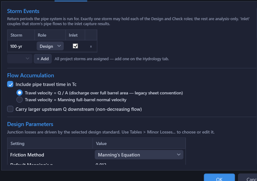
| Include pipe travel time in Tc | Off | Rational modes only (Manual, or HydraLink on the Basin Parameters basis). Accumulates Tc downstream as max(upstream Tc + pipe travel time, local inlet time). Off means each node uses its own inlet time alone. |
| Travel velocity basis | Q / Afull | Radio buttons beneath the checkbox (active only when it's on): which velocity converts pipe length to travel time. Q / Afull: discharge over the full-barrel area, the legacy DFW spreadsheet convention (also matches the Excel export). Manning full-barrel normal velocity: from geometry and slope only, flow-independent, slightly conservative at partial flow. |
| Carry larger upstream Q downstream | Off | Rational modes only (same two), and it touches Q, never Tc. When on, a node's computed peak flow never drops below the total flow arriving in its incoming pipes (TxDOT-style "use the higher discharge"). Off accepts standard practice: Q = ΣCA·i(system Tc) may decrease downstream as Tc growth lowers intensity. |
| Accumulate Flows | On | Shown in Peak Flows Only mode and on the HydraLink Fixed Flows basis: the two cases where directly entered or imported flows drive the network. Whether those flows sum downstream through junctions. Off means each pipe uses only its upstream node's flow. The rational method always accumulates ΣCA, so this switch has no meaning in the rational modes. |
Friction Method
| Setting | Description |
|---|---|
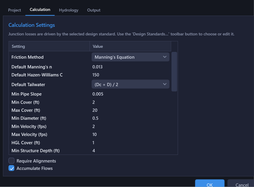
| Friction Method | Manning's equation (default) or Hazen-Williams equation. Applies project-wide. |
| Default Manning's n | The n of every pipe whose Civil 3D part states none and that has no n entered (default: 0.013). Changing it moves those pipes with it, and the calc messages name them. An n entered on the results grid or the culvert panel stays as entered. |
| Default Hazen-Williams C | Default smoothness coefficient when Hazen-Williams is selected (default: 150). |
Tailwater
| Setting | Description |
|---|---|
| Default Tailwater Method | How to compute the downstream boundary condition at outfalls:
|
Design Constraints
| Setting | Default | Description |
|---|---|---|
| Default Circular Family | First circular family in the parts list | Part family a pipe re-points to when its shape is switched to Circular. Without a pin here, the switch lands on the first circular family in the drawing's parts list, which can land on PVC in an RCP design. |
| Default Box Family | First box family in the parts list | Same as above, for a switch to Box. |
| HGL Method | Gradually Varied Flow | Which construction draws the HGL inside each barrel: Gradually Varied Flow (the rigorous engine), Simplified Normal Depth, or Simplified Normal Depth (Crown Reset), the two hand-reproducible conventions a municipal reviewer checks against. Sizing and the results grid always read the same setting, so they can never disagree. |
| Min Slope Basis | Fixed Value | How the minimum slope floor is resolved, per pipe size: Fixed Value uses the Minimum Pipe Slope scalar for every size (legacy default); Velocity-Based derives each size's minimum from the slope that reaches Min Velocity flowing full (the self-cleaning basis municipal per-diameter tables are built from, letting large trunks run flatter than the scalar); Greater of Both keeps the scalar as an absolute floor under the velocity-based value. Auto Design and the compliance grid's Min Slope check both resolve through this setting, so they never disagree. |
| Min Diameter | Smallest catalog size | Smallest allowable pipe size for Auto Design. Chosen from a drop-down of the actual sizes in the Default Circular Family, or the first circular family in the parts list when none is set, since a minimum that isn't a size you can buy would either exclude every candidate or none of them. A note under the field names the family the list came from; changing Default Circular Family updates the list. Every pipe is held to the minimum, whatever its family; a box is held to it by rise. If the drawing has no pipe parts list, the field falls back to plain numeric entry and says so. |
| Minimum Pipe Slope | 0.005 ft/ft | The scalar under Min Slope Basis = Fixed Value (or the floor under Greater of Both); unused under Velocity-Based. Pipes below the resolved minimum trigger a warning. |
| Min Velocity | 2.0 ft/s | Judged as Manning full-flow velocity Vf (flow-independent, from geometry and slope). Pipes below this trigger a compliance warning (self-cleaning velocity), and it is the basis for Velocity-Based Min Slope above. |
| Max Velocity | 10.0 ft/s | Judged as Q ÷ Afull (discharge over the full-barrel area), independent of the flow depth actually present. Pipes exceeding this trigger a compliance warning. It gates pipe size in Auto Design: a size that clears it may still ride as steeply as cover, crossings, and HGL allow, and it is never a grade limiter. |
| Minimum Pipe Cover | 2.0 ft | Minimum clearance from ground to pipe crown. |
| Maximum Pipe Cover | 20.0 ft | Maximum depth from ground to pipe crown. |
| HGL Cover | 1.0 ft | Required clearance from the hydraulic grade line to ground/rim, checked at every computed storm. |
| Minimum Structure Depth | 4.0 ft | Minimum depth from rim to lowest connected pipe invert at each access structure (manhole, inlet, junction box). Not enforced at fittings/null structures (see Fitting Keywords below); the sizing engine never buries the barrel itself to satisfy this, only deepens the structure's sump. |
| Min Crossing Clearance | 1.0 ft | Required vertical clearance between this network's pipes and any crossing pipe (other storm lines, or water/sewer utilities referenced through data shortcuts). Crossings with less clearance are flagged in red in the profile view, and Auto Design grades pipes to maintain this distance. Project-specific; the last value you set becomes the default for new projects. |
HGL Cover (Check) is not a row in this dialog (there's no field to type it into directly), but a design standard's design criteria can carry a separate check-storm HGL cover value, which arrives (like everything else in that checklist) through the design-criteria adoption prompt when you apply the standard.
Alignment Configuration
| Setting | Description |
|---|---|
| Require Alignments | When enabled, pipes must be assigned to an alignment to be included in calculations. |
| Alignment Sort Order | Alphabetical (by name) or Hydrologic (trunks first, then laterals downstream-to-upstream). |
Alignment design types (Storm Drain / Culvert / None) are not set here: they're edited from Tables > Alignment Types.... See Alignment Design Types.
Compliance Checks
Below the Design Constraints table, every design-criteria check (velocity, cover, HGL clearance, etc.) has its own Enabled / Disabled toggle. Disabling a check removes it entirely from the Comply column: its rows in the results grid no longer factor it into the pass/total score, and its per-pipe warnings are suppressed. This is a project-wide switch; for a one-off accepted violation on a specific pipe, use the per-pipe Acknowledge Check Failures... right-click action instead, which preserves an audit trail. See Compliance Checking.
Auto Design & Matching Defaults
| Setting | Default | Description |
|---|---|---|
| Auto Design Engine | Phased | Phased (size, then profile, then HGL) is the default; a project saved before it became the default opens on Phased too; pick Classic here to put it back. Classic is the long-standing engine. See Auto Design Engine for what each one does and does not propose. Hold-existing-grades mode (below) always runs Classic regardless of this choice. |
| Auto Design Grades | Design Grades | Design Grades lets Auto Design propose new inverts (an efficient, buildable profile). Hold Existing Grades locks every invert to the drawing and renders size-only verdicts at the locked grade (StormCAD-style parity); drop connections, splits, and downstream-lowering suggestions don't apply in this mode. |
| Sizing Capacity Basis | HGL-Governed | Gravity Full-Flow never proposes a size where Q exceeds full-barrel capacity (no surcharge). HGL-Governed allows pressure flow when the computed HGL still clears HGL Cover below grade, common North Texas practice. Compliance-grid checks are unaffected either way. |
| Max Surcharge Ratio (blank = off) | Off | Optional ceiling on (HGL − crown) / rise that the Phased engine sizes to under HGL-Governed. Off by default: HGL Cover and the velocity limits already limit surcharge, so surcharge above the crown is not its own criterion unless you set one. Ignored under Gravity Full-Flow. |
| Auto Design Size Changes | Never | How Auto Design handles a mid-run size increase: Never (upsize whole run), Prompt before adding a split, or Add automatically at a size-change null structure. Never by default: a break is a new structure, and the extra cost can outweigh what it saves. |
| Min Split Leg Length (ft) | 20.0 ft | Shortest leg Auto Design will create when splitting a pipe for a size change. |
| Split Station Rounding (ft) | 1.0 ft | Station increment new split points are rounded to (rounding up, always conservative). |
| Drop Connections | Not Allowed | Whether Auto Design may seat an incoming pipe above the match-criteria transition at a real structure (a drop connection), buying trench depth on the run above at the cost of a plunge in the structure. Off by default: that trade is a site/cost call for the engineer. |
| Max Added Drop at Structure (ft) | 0 (no limit) | Largest drop Auto Design may add above the match criteria when Drop Connections is on. Bounds only the discretionary ride, never a crown/centerline match step. |
| Max Pipe Grade (Auto Design, 0 = none) | 0 (off) | Optional. With a value set (ft/ft), caps how steep the Phased engine may leave any single pipe. Where an efficient profile would otherwise put a run's whole drop into one pipe (a short connector plunging into a fixed outfall, an inlet stub over a deep junction), the excess fall is spread across the run instead. Minimum slope and crossing clearances are never given up for it. Not a compliance criterion and never a sizing factor; at the default 0 the cap is off and a very steep pipe gets a deeper-inlet advisory instead. Applies only to the Phased engine. See Proposed Grades. |
| Cover Grade Breaks | No | Whether Auto Design may propose same-size grade breaks that follow sampled ground under mid-span humps, to save trench depth. Off by default: a TIN surface can undulate, and an engine free to chase every dip would litter the run with break structures. |
| Min Grade-Break Leg Length (ft) | 100.0 ft | Shortest leg a cover-following grade break may produce. Deliberately larger than Min Split Leg Length, which governs size-change splits. |
| Fitting Keywords | wye, bend, tee, lateral, elbow, reduce, pipe size change, PC, PT, exit, headwall, curve | Comma-separated part-description keywords, matched as whole words (so "tee" does not hit "Steel"). A match excludes the structure from the Minimum Structure Depth check and the drop-connection ride, and makes a real (non-null-structure) part eligible to be classified as a wye/bend/size-change fitting for the Lateral Match at Wyes rule below and for Label Fittings; a structure that is not a fitting falls under Lateral Match at Structures instead. Remembered as your default for new projects. |
| Inlet Keywords | inlet, catch basin, curb, grate, combination, CB | Comma-separated, whole-word part-description keywords that classify a structure as an inlet at import/load, and that HydraLink basin matching prefers when placing a basin. |
| Structure Drop (ft) | 0.1 ft | Default invert drop applied at each real structure when computing pipe slopes under the Inverts match criterion. |
| Ignore Null Structure Drop | Yes | When Yes, the Structure Drop is not applied at null (pipe-to-pipe) structures. |
| Match Criteria (Slopes + Auto Design) | Inverts | Default structure transition criterion (Inverts, Centerlines, or Crowns) for new multi-pipe slope operations, and for every pipe-to-pipe transition Auto Design proposes during sizing (including a size-change split). Inverts applies the Structure Drop through the transition; Centerlines and Crowns don't. |
| Lateral Match at Wyes | Centerlines (new projects); Same as network (projects saved before this setting existed) | Overrides the match criterion at a wye (a null structure, auto-joint, or Fitting Keyword part with exactly two pipes in and one out). The trunk inlet (the straight-through one) always holds invert continuity, whatever this setting says; the lateral is matched by this setting instead of by Match Criteria above. Same as network turns the rule off: every incoming pipe, wye or not, follows Match Criteria. A manhole receiving a lateral is never treated as a wye, and an eligible structure with three or more inlets is reported in Network Issues rather than matched as one. Read by both Auto Design engines and the multi-pipe slope tools. |
| Lateral Match at Structures | Crowns (new projects); Same as network (projects saved before this setting existed) | How a lateral entering a real structure (a manhole, inlet or junction box) matches the main. The trunk inlet (the one continuing the main) keeps Match Criteria; every other inlet is matched to the main by this setting, never stepping less than the Structure Drop (Inverts applies the drop alone). Same as network turns the rule off. Read by both Auto Design engines and the multi-pipe slope tools. Remembered as your default for new projects: a new project starts at whatever you chose last (Crowns until you have chosen), never at a value a design standard supplies. |
| Auto-Update K Values | No | Whether junction Kj values recompute automatically as geometry changes. |
| Alignment Sort Order | Alphabetical | Alphabetical (by name) or Hydrologic (trunks first, then laterals downstream-to-upstream). Also listed under Alignment Configuration above. |
| Merge Splice Rows | No | When Yes, pipe-splice reaches (several real pipes shown as one continuous run) are merged into a single read-only row in the results grid. |
Quantity Takeoff
Cut-depth class boundaries for the pipe linear-footage breakdown in the quantities table (Output ▾ > Tables to Drawing > Quantities Table and the Excel Quantities sheet). Cut depth is measured from the sampled surface to the flowline invert; each row is a class upper bound, and the last class is open-ended. Remove all rows to skip the depth breakdown entirely.
Design Standard (Not in This Dialog)
The active design standard (junction loss library) is not selected in Project Settings: it's chosen from the Design standard dropdown at the top of Tables > Minor Losses.... The Storm Drain tab above only reminds you of this ("Junction losses are driven by the selected design standard. Use Tables > Minor Losses... to choose or edit it."). Built-in standards include:
- User Starter: Generic loss types with simple K expressions. Good starting point for custom standards.
- HEC-22: HEC-22 4th Edition standard types, using the 3-step access hole energy loss method for manholes.
- iSWM / NCTCOG: NCTCOG iSWM 2014 types, using the HEC-22 2nd Edition compound K method for manholes.
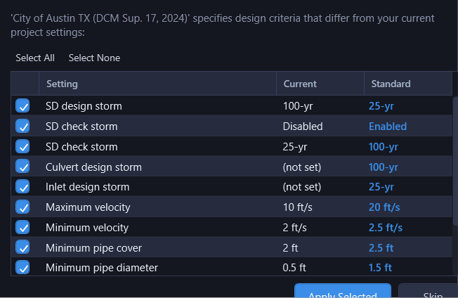
When a standard includes design criteria (municipality-specific defaults for storm periods, velocity limits, cover, etc.), HydraStorm prompts you with a checklist showing which settings differ from your current project. Accept or decline each recommendation individually.
Design Criteria Prompting
If you switch from the User Starter standard to the HEC-22 standard and the HEC-22 standard recommends a 100-year check storm, HydraStorm shows a dialog listing the differences. Check the ones you want to apply and click OK. This is a one-time prompt when the standard changes; it does not override settings you change later.
Hydrology Tab
Where runoff comes from. Detailed on the Hydrology Modes and Storm Events pages. The tab has two sub-tabs, General and IDF Curves, below the hydrology mode selector. Which storms each module runs lives on that module's own tab, not here.
Hydrology Mode
Always visible at the top of the tab, as radio buttons:
| Mode | Description |
|---|---|
| Peak Flows Only | Enter Q (cfs) directly at each node. No rational method. |
| HydraLink | Import from a HydraLink project (.hyd). Selecting this mode reveals a HydraLink Integration section on the General sub-tab (file path/browse/reload, the plan picker directly under the file (picking a plan computes the flows), Import Basis, spatial match radius, and a flow-assignment review grid). Import Basis chooses what the link supplies: Basin Parameters (C·A·Tc, HydraStorm computes Q) or Fixed Flows (routed results drive Q). The linked file can force one of them, in which case the radios lock and the line beneath explains why; see Import Basis. |
| Manual | Enter area, C, and Tc per node for rational method calculation. |
General Sub-Tab (rational options and defaults)
Hidden in Peak Flows Only mode, where there is nothing to configure: flows are entered per node on the results grid.
| Setting | Default | Description |
|---|---|---|
| Apply Storm Frequency Adjustment Factor (Cf) | Off | Multiplies the runoff coefficient by the storm's Cf: Q = (Cf·C)·I·A. Reveals the Cf table below; see Frequency Adjustment (Cf). Disabled in HydraLink mode: the linked file's storm K factors drive it. |
| Apply Rational Unit Conversion Factor | Off | When checked, multiplies peak flow by the Conversion Factor (default 43,560 / 43,200 ≈ 1.0083) that converts acre·in/hr to cfs. Most engineers leave this off since the bias is <1%. |
| Default Inlet Time | 10 min | Time of concentration for overland flow to reach the first inlet. |
| Default C | 0.70 | Default runoff coefficient applied to nodes with no basin data of their own. |
| Minimum Tc | 0 min | Floor applied to the time of concentration before every intensity lookup. Most municipal standards floor Tc at 10 min, and NOAA Atlas 14 publishes nothing below 5 min; below the table minimum the interpolator clamps to the shortest duration and under-predicts i. 0 disables the floor. |
The three defaults stay editable in HydraLink mode: they are the fallback for nodes with no matched HydraLink basin.
Storm Events
The Storm Events table is where the project's return periods are declared, one row per storm, with its Cf. Type a return period into the box below the table and click Add; Remove deletes the storm from the project and from every module that was analysing it.
This list is the single source of the project's storms. Two things follow from it:
- The Storm Drain, Culverts and Inlets tabs assign roles (design, check, analysis) by picking from this list, rather than each defining its own return periods.
- The IDF Curves sub-tab gets one intensity column per row, so a published municipal table can be entered in full, including storms you have not yet assigned to a module.
Removing a storm from a module tab only unassigns it. The storm, its Cf and its intensity column stay, so switching a module off a storm and back on again does not cost you the data.
Frequency Adjustment (Cf)
Checking Apply Storm Frequency Adjustment Factor (Cf) enables the Cf column of the Storm Events table above. This is the only place Cf is entered. Every module (storm drain, culverts, inlets) looks its Cf up there by the return period it is running at, and each module's storm grid shows the resolved value read-only.
Cf is a property of the storm, not of the analysis: a 100-year storm has the same frequency adjustment whether you are checking a trunk line, a culvert, or inlet spread. Entering it once is what keeps those runs consistent: a 100-year culvert check resolves the 100-year Cf even when the storm drain is sized for the 5-year storm.
A new storm's Cf is seeded from the TxDOT/FHWA standard values, which you can overwrite:
| Return period | Cf |
|---|---|
| 10-year and under | 1.00 |
| 25-year | 1.10 |
| 50-year | 1.20 |
| 100-year and over | 1.25 |
Unchecking the box greys the Cf column but keeps its values, so switching the adjustment back on restores what you entered. In HydraLink mode the table is read-only: the linked file's per-storm K factors own it, and HydraStorm adopts them by matching return period.
Projects saved before this release carried Cf per storm row on each module tab. Opening one migrates those values into the table, preferring the storm drain row (the only copy the calculation engine ever read) and falling back to the stored design/check factor. The migration is logged, and nothing is written to your file until you save.
IDF Curves Sub-Tab (hidden in Peak Flows Only mode)
Configures rainfall intensity-duration-frequency data for the rational method:
- Import controls (hidden in HydraLink mode, where IDF comes from the linked file): Latitude/Longitude fields with a Pick Point button (samples a point in the drawing), Fetch NOAA Atlas 14, and Import CSV.
- Interpolation Method: radio buttons: Log-Log (log-log interpolation on the intensity table; standard for Atlas 14 data), Linear (linear interpolation on the table), or b/d/e Coefficients (evaluates i = b / (Tc + d)e within its fitted duration window).
- Duration / Intensity Table: editable grid of duration vs. intensity, with one column per storm on the Storm Events list, headed by return period and role. Enter a published municipal table here directly; blank cells simply omit that duration for that storm. The standard durations (5, 10, 15, 30, 60, 120, 180 min) are always present, and Add duration adds any other the manual publishes (20, 25, 40, 45, 90 min) up to 180 min. Remove on a row deletes that duration for every storm.
- b/d/e Coefficients section (shown when Coefficients mode is selected): one editable row per storm with an R² fit-quality readout. b is the numerator, d the time shift (minutes), and e the exponent in
i = b / (Tc + d)e. Generate from Table fits a curve for every storm the table has at least three durations for (durations up to 2 hours) and reports any it could not; editing a coefficient by hand resets that row's R² to “—”, since the fit statistic no longer describes the curve. - IDF Curve chart: a log-log intensity-duration chart reflecting the current table/coefficients and interpolation method.
See the IDF Data page for more detail on each source.
Why OK Can Refuse
Clicking OK validates the hydrology configuration before committing it, and two conditions block the commit outright rather than just warning:
- A storm the IDF data can't price. If a configured storm's return period has no usable table row or coefficient fit, OK refuses and names the storm. Add the missing intensity data (or remove the storm from every module) before continuing.
- A reachable pond under a rational hydrology mode. Storage attenuates flow; Σ(C·A) does not. If a linked HydraLink pond connects to a structure HydraStorm models (the routine case of continuing the model below a detention pond), rational accumulation can't be trusted for the network, and OK refuses. The message names the pond and tells you to solve the plan in HydraLink: HydraStorm finds the plan's published results automatically (by its
<hyd>_<plan>.hlresultsname, beside the.hydor the plan's.hlparcels, or the path set in HydraLink's CAD Link Settings), reads the pond's routed outflow from them, and on Reload (or the next time the dialog opens) moves the import basis to Peak Flows so the trunk above it prices from that number instead of un-attenuated ΣCA. A pond at the outfall with nothing modeled below it is not "reachable" and never triggers this. Never delete the pond to work around the refusal: the storage is real. Failing that, switch the project to Peak Flows Only and enter the flows by hand. See HydraLink Integration.
Culverts Tab
Storm events for alignments classified as culverts, in the same Storm / Role / Cf grid as the storm drain (Cf read-only here too, resolved from the return period). Storms are picked from the project's Storm Events list. Leave the grid empty to run culverts on the storm drain storms.
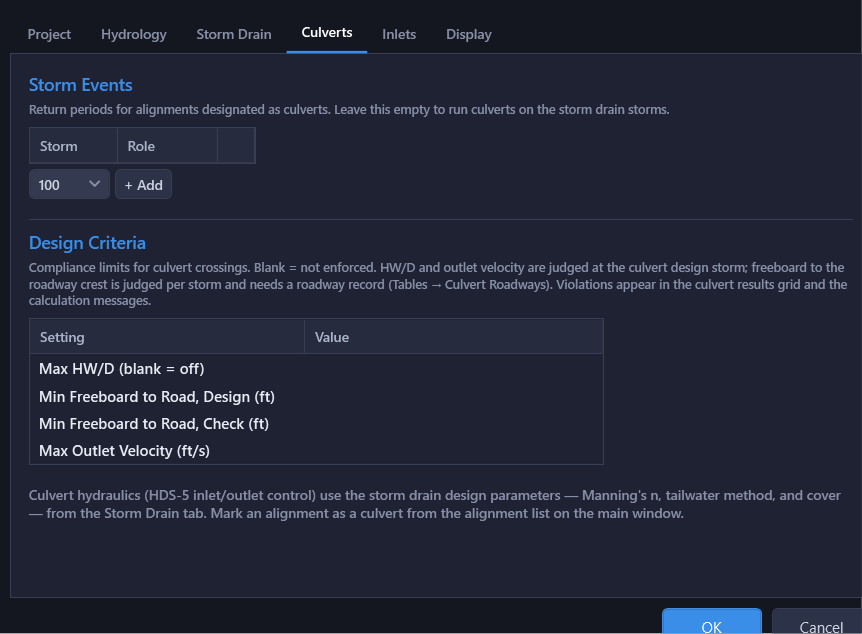
Culvert hydraulics (HDS-5 inlet/outlet control) use the storm drain design parameters: Manning's n, tailwater method, cover. An alignment is marked as a culvert from the alignment list in the main window; see Culvert Analysis.
Design Criteria
Below the storm grid, four compliance limits for culvert crossings, separate from the storm drain's own Design Constraints on the Storm Drain tab. Each is blank by default, meaning not enforced.
| Setting | Description |
|---|---|
| Max HW/D (blank = off) | Maximum headwater-to-rise ratio at the design storm. |
| Min Freeboard to Road, Design (ft) | Minimum clearance from the design-storm headwater to the roadway crest. Needs a roadway record (Tables > Culvert Roadways...) to evaluate; without one, an advisory reports the check was skipped rather than failing it. |
| Min Freeboard to Road, Check (ft) | Minimum clearance at the check storm. 0 means the road must not overtop at the check storm. |
| Max Outlet Velocity (ft/s) | Maximum barrel outlet velocity at the design storm. |
Verdicts appear in the culvert results grid's Criteria column, in calculation messages, and in the Excel export's culvert sheet. A design standard can prescribe these values too, arriving through the same design-criteria adoption prompt as its other recommended settings. See Culvert Analysis > Design Criteria for detail, and Roadway Overtopping for the roadway record itself.
Inlets Tab
The Enable inlet design checkbox turns the module on: the Inlet tab in the main window, the inlet capacity and bypass calculations, and the storm grid below it. The storm grid works like the storm drain's, picking from the project's Storm Events list; leave it empty to run inlets on the storm drain storms.
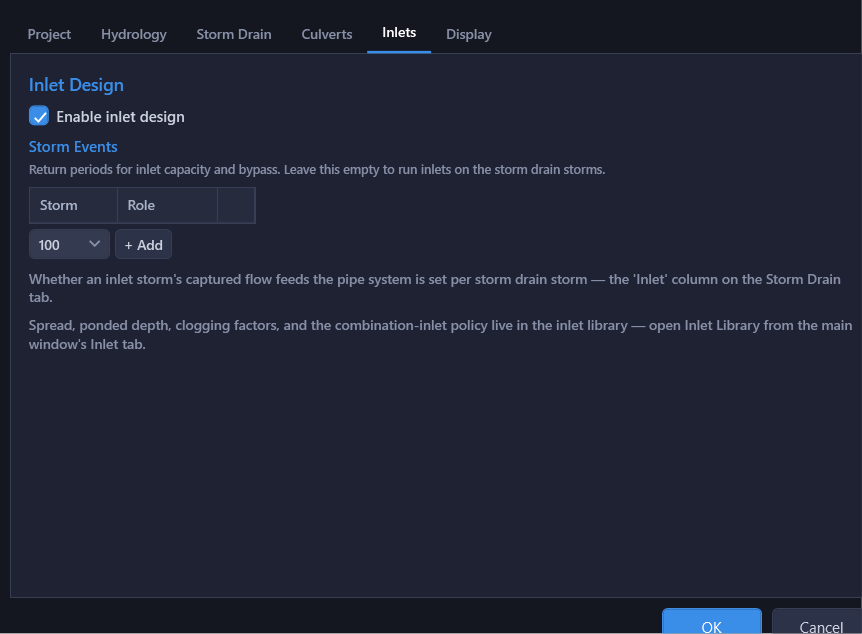
Whether an inlet storm's captured flow feeds the pipe system is set per storm drain storm: the Inlet column on the Storm Drain tab.
Spread, ponded depth, clogging factors, and the combination-inlet policy are not here; they live in the inlet library, opened from the Inlet tab's Library... button in the main window. See Inlet Analysis.
Display Tab
One row per quantity (flow, velocity, elevation, …) setting the decimal places shown in the results grids, drafted CAD tables, and the Excel export. Display only. Calculations always use full precision. Default keeps each output's built-in format, which can differ per column; picking a number makes every output agree on that quantity.
The Station row is the one exception: stations always render in plan-and-profile "+" notation (e.g. 12+34.56), on the results grid, the drafted storm-calcs CAD table, and the Excel workbook alike, and the "+" itself never changes. What the Station row sets is the number of digits after the plus: the same row reads 12+34.6 at one digit. Default is two digits, matching the Civil 3D display convention.
Profile view colors, line styles, and overlays are per-user and live on View ▾ > View Settings, not here.
Not in This Dialog
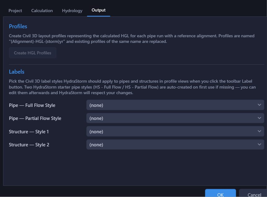
- Label styles: picking and applying them is one action on Output ▾ > Apply Label Styles…. See Profiles & Labels.
- HGL profile creation: Output ▾ > Create HGL Profiles... opens an options dialog for storm selection, profile style, and full vs. Simple HGL.
- Design standard: the Design standard dropdown (and Manage button) at the top of Tables > Minor Losses....
- Inlet library: the Inlet tab's Library... button.
Project settings are saved in the .hsp project file. Each project has its own methodology, hydrology mode, design standard, inlet library, and output configuration. User-level preferences (custom library paths, profile view colors, default fitting keywords) are stored separately in Program Settings at %LocalAppData%\HydraStorm\settings.json.