Profiles & Labels
Create Civil 3D layout profiles and apply label styles for plan production.
HGL Profiles
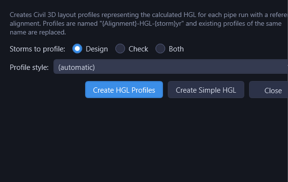
From the Output ▾ menu, click Create HGL Profiles... to open the options dialog. It generates Civil 3D layout profiles representing the computed HGL for each pipe run with a reference alignment.
- Storms to profile: Design, Check, or Both. This row is hidden (and every create collapses to Design) when neither the storm drain nor the culvert module has a check storm.
- Profile style: a Civil 3D profile style to apply, or (automatic) to match the style of an existing profile on the alignment.
Two create buttons share the storm and style selections:
- Create HGL Profiles: the full water-surface profile, including the gradually-varied-flow surface PVIs inside pipes flowing partially full.
- Create Simple HGL: PVIs at each pipe's upstream/downstream HGL and each structure's HGL only, with no interior curvature points. Use this when you plan to label profile PVI points: the full GVF surface would put a label on every curvature point along a partial-flow pipe.
Profile naming: {Alignment}-HGL-{storm}yr (e.g., "Main-St-HGL-10yr"). When one alignment carries more than one run (two culvert crossings on one road alignment, or storm drain branches assigned to one alignment), each profile carries its run's downstream structure so none overwrites another: {Alignment}-{Structure}-HGL-{storm}yr (e.g., "FM-1171-EW-2-HGL-100yr"). A profile with the same name already on the alignment is replaced.
Culverts: culvert alignments are profiled too, at the culvert module's own design and check storms (the storms the culvert table reports), so a culvert profile's name carries the culvert storm. The line starts at the water surface at the outlet, follows the water surface through the barrel, and rises at the entrance to the headwater pool: the same line the Culvert tab's profile draws. Where the barrel flows full, the line is the pressure line: a submerged outlet starts at the tailwater, and the line climbs through the full barrel at its friction slope. Side-by-side barrels at one crossing draft one profile, from the barrel with the higher headwater. Create Simple HGL keeps just those three points per barrel. A barrel with no flow is not drawn.
The dialog stays open after each create and shows the result inline, so you can re-run with different storm, style, or flavor choices without reopening the menu. Your selections are remembered per project; the Output menu's out-of-date badge and the "Update Outdated" action in Output > Drafted Outputs re-draft using the same storm, style, and flavor.
HGL profiles draft into an existing profile view. If you don't have views set up yet, use Create Profile Views to draft complete, ready-to-annotate views for the network first.
Label Styles
From the Output ▾ menu, click Apply Label Styles…. The dialog is where you both pick the styles and apply them: it stays open after an apply and reports the result inline, so you can swap a style and re-run without reopening the menu. Five label style slots are available, each with a (none) option that skips that label:
| Slot | Purpose |
|---|---|
| Pipe: Full Flow Style | Label for pipes flowing full (at or above capacity) |
| Pipe: Partial Flow Style | Label for pipes flowing partially full |
| Structure: Style 1 | Primary structure label |
| Structure: Style 2 | Secondary structure label (for additional info) |
| Structure: Junction | Drafted instead of Style 1 where three or more pipes meet (a lateral tying in, a confluence, or a split). Style 2 is unchanged. Leave it on (none) and a junction reads like any other structure. |
The junction slot is decided from the network, not from the line being drawn. A structure where a lateral ties in carries the junction label in the trunk's profile view and in the lateral's own view (where the same structure is that run's downstream end), because that is how a junction is annotated on a plan sheet. A structure with two laterals still gets one label. Null structures that are really wyes count as junctions too.
These same slots also appear in the Create Profile Views dialog's Part labels group: setting them in either place sets them in both. The difference is placement: this action labels every part in every profile view, while Create Profile Views labels one per run of unchanging pipe.
HydraStorm auto-creates two starter label styles ("HS - Full Flow" and "HS - Partial Flow") if they don't exist in the drawing. You can customize these in Civil 3D's label style editor.
A Saved Style This Drawing Doesn't Have
Each slot lists only the styles this drawing actually has. A style saved against a different drawing is not offered: its combo comes up blank and a note above the slots names it, so you find out here, before you click Apply, rather than discovering afterward that nothing got labelled. This dialog has no OK to clear a stale name on. It edits the project's saved styles live as you touch each combo, so a name it can't offer is left alone rather than cleared just by opening the dialog: it stays saved, un-applied here, until you pick a replacement and Apply. An empty style list is read as nothing to check against, not "this drawing has none," so it never clears a saved name on its own.
Label styles are stored per project in the .hsp file. They are not part of the Project Settings dialog: picking and applying them is the one action described above.
Profiles and labels are created using Civil 3D's standard profile and label objects. You can further customize them using Civil 3D's built-in style editors after HydraStorm creates them.